Foot training device and foot training method

a training device and foot technology, applied in the field of foot training devices and foot training methods, can solve the problems of complex structure of the device disclosed in patent literature 2, inability to replace the elastic member of the training device, and difficulty in changing so as to achieve different degrees of elasticity in the flexure, easy to change the magnitude of the load, and simple structure

Active Publication Date: 2021-08-05
NASYU CO LTD
View PDF0 Cites 0 Cited by
  • Summary
  • Abstract
  • Description
  • Claims
  • Application Information

AI Technical Summary

Benefits of technology

[0017]According to the present invention, it is possible to provide a foot training device having a simple structure and making it possible to easily change the magnitude of the load.
[0018]The foot training device according to the present invention includes the fulcrum placed at a center, the four projections projecting from the fulcrum, each of the four projections having, at least in a portion thereof, an elastic member that is bendable in the bending direction. At least two of the four projections have different degrees of elasticity in flexure as determined when a force is applied to the distal end of each of the at least two projections to bend the elastic member. Thus, the magnitude of the load can be easily changed by selecting the projection to be used during training.
[0019]“Degree of elasticity in flexure” means the bendability of a projection when it is bent. The higher the degree of elasticity in flexure, the harder it is to bend the projection, and the higher the training load. In the case where each elastic member is formed of a plate-shaped or rod-shaped member made of a resin material or a rubber material, the degree of elasticity in flexure of an elastic member is increased by increasing the flexural modulus or the cross-sectional area of the constituent material, and is increased by reducing the length of the constituent material. The degree of elasticity in flexure of a projection is increased by increasing the degree of elasticity in flexure of the elastic member forming the projection, and is also increased by reducing the overall length of the projection. That is to say, the degree of elasticity in flexure of the projections can be varied by adopting a configuration in which the projections have different lengths or a configuration in which the elastic members constituting the projections have different flexural moduli or different cross-sectional areas. With the configuration in which the projections have different lengths, it is easy to vary the degree of elasticity in flexure of the projections. On the other hand, with the configuration in which the elastic members constituting the projections have different flexural moduli or different cross-sectional areas, it is easy to greatly vary the degree of elasticity in flexure of the projections, and excellent variety of load is thus obtained. Note that the flexural modulus of an elastic member means a value obtained from the amount of displacement (strain) that occurs in the elastic member when it is bent and the amount of force applied.
[0020]Varying the length of the projections means the following: it is sufficient that the overall length of the projections from the fulcrum to the respective distal end is varied, and the length of the elastic members constituting the projections may be varied, or the length of portions other than the elastic members may be varied. When the overall length of projections is varied, due to leverage, for example, in the case where the elastic member of a longer projection is bent and stretched by holding the distal end of the projection, the elastic member can be bent and stretched with a smaller amount of force than in the case where the elastic member of a shorter projection is bent and stretched by holding the distal end of the projection. That is to say, a longer projection has a lower degree of elasticity in flexure, and accordingly a lower training load, than a shorter projection. Also, a longer elastic member itself constituting a projection has a lower degree of elasticity in flexure, and accordingly a lower training load.
[0021]In particular, with regard to the structure of the training device including the four projections, a training device in which the four projections project in cross directions from the fulcrum at the center, and, for each pair of projections that oppose each other across the fulcrum, the projections are arranged on a straight line is suitable for foot training. In particular, a configuration in which all of the four projections have different lengths makes it possible to select at least four different levels of load and is therefore particularly preferable.
[0022]The training device according to the present invention is suitably used as a foot training device for improving the muscle strength of a sole by bending and stretching a projection using muscles of a sole. As a specific example of the method for improving the muscle strength of a sole, a method is conceivable, as described above as the foot training method according to the present invention, the method including the steps of: placing the training device on a floor surface or the like, bringing a heel of a foot into contact with the training device, hooking a toe around an end edge of the distal end of at least one of the projections, pulling up the distal end of the projection in this state, and bending and stretching the projection using muscles of a sole. Moreover, another training method is also conceivable, the other method including the steps of: holding one of the projections of the foot training device between two adjacent toes of a foot, bringing a heel of the foot into contact with the training device, pulling up the projection in this state, and bending and stretching the projection using muscles of a sole. It is possible to effectively strengthening the muscles of a sole, mainly a transverse arch portion and a medial longitudinal arch portion, by performing these training methods.

Problems solved by technology

However, since a heavy weight is applied to the training device during use, the training device needs to have a structure that is strong enough to resist the heavy weight, and, in many cases, the structure does not allow for replacement of elastic members of the training device.
Even if replacement is possible, it is necessary to prepare a plurality of elastic members, and therefore, it is not easy to change the magnitude of the load.
However, the training device disclosed in Patent Literature 2 has a complex structure compared with the training device disclosed in Patent Literature 1.
Moreover, although various training devices for improving the muscle strength of the arms, legs, trunk, and the like are known including those disclosed in Patent Literature 1 and Patent Literature 2, training devices for improving the muscle strength of the feet including a sole are not much used.

Method used


Image

  • Foot training device and foot training method
  • Foot training device and foot training method
  • Foot training device and foot training method

Examples


Embodiment Construction

[0032]Structure of Foot Training Device

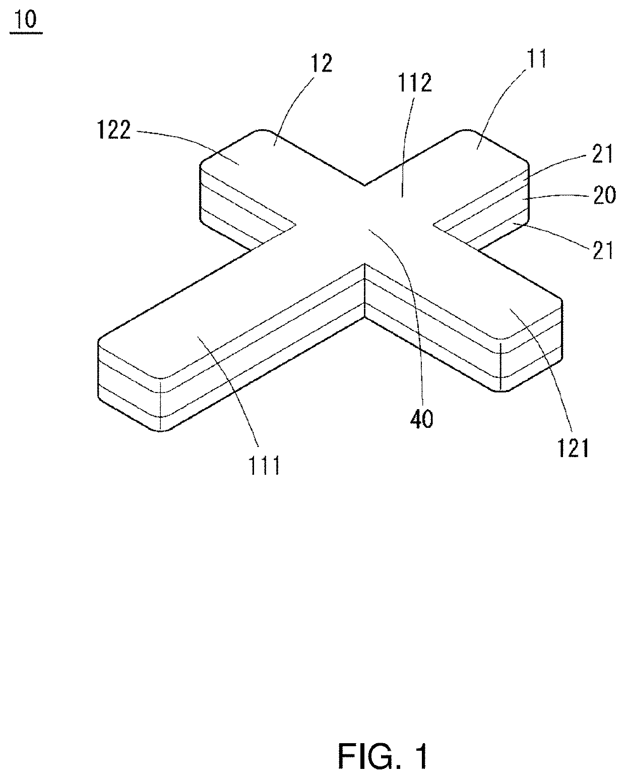
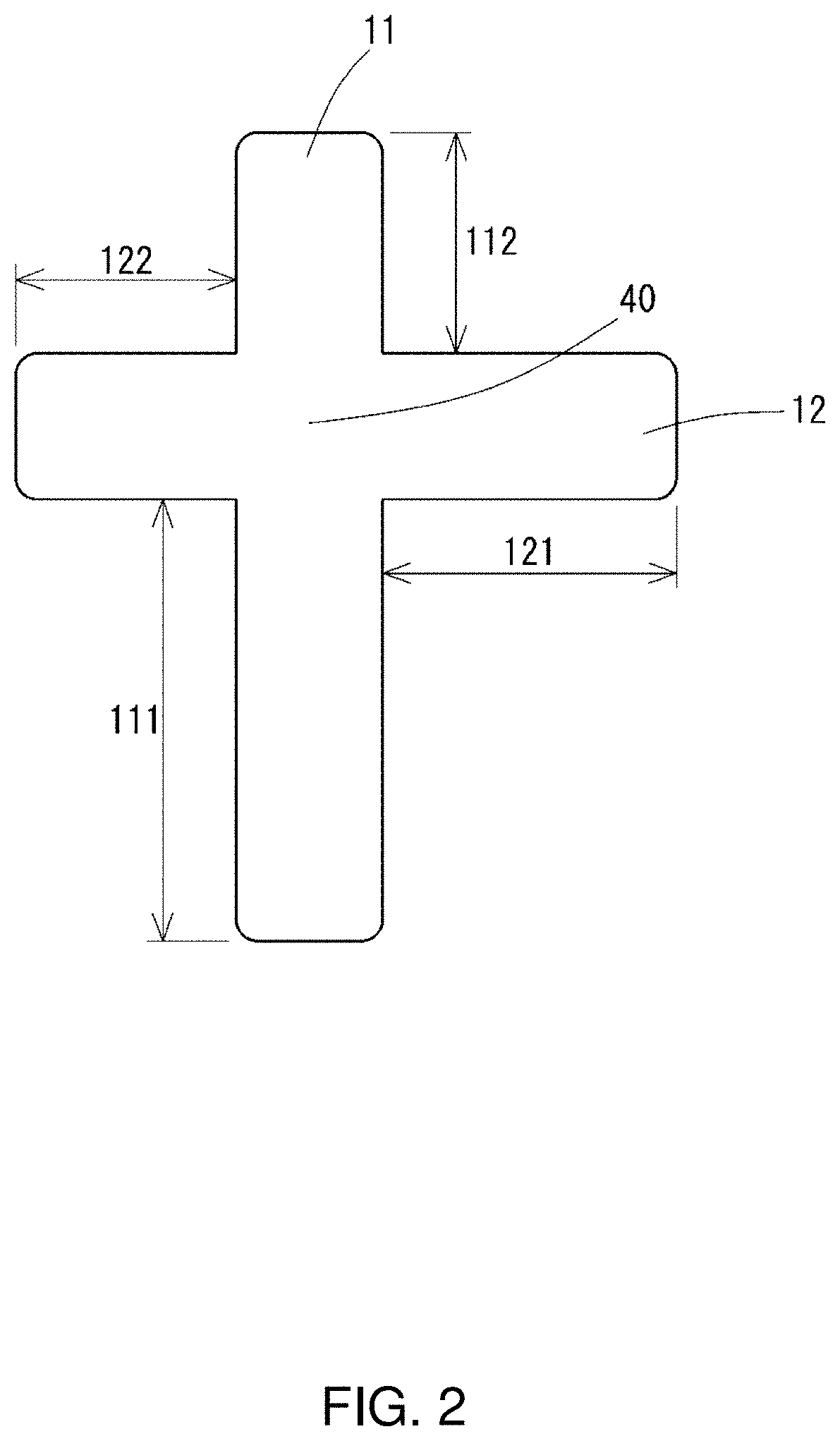
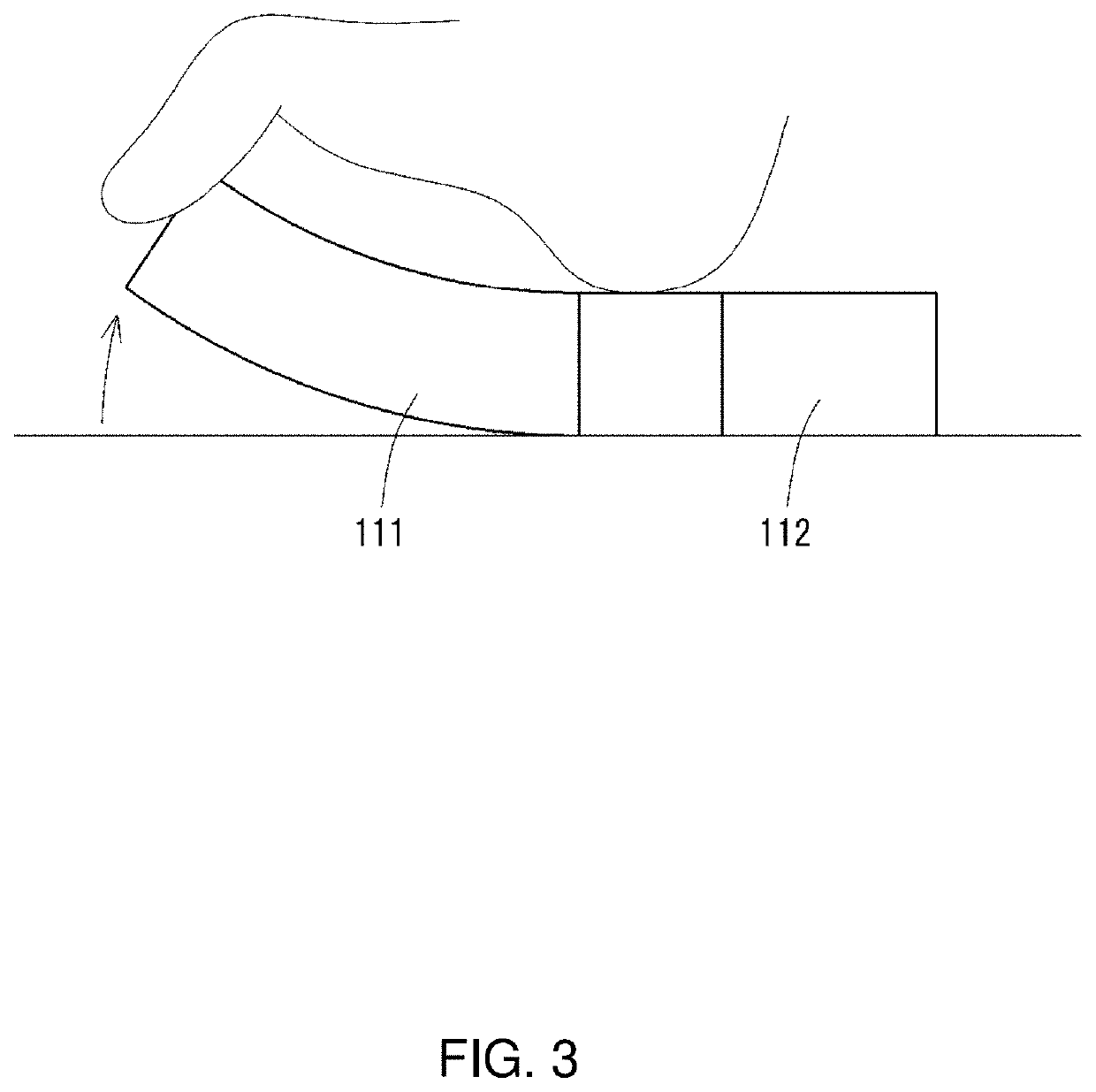
[0033]A foot training device according to an embodiment of the present invention will be described in detail with reference to the drawings. FIG. 1 is a perspective view showing the external appearance of a foot training device according to an embodiment of the present invention, and FIG. 2 is a top view of the foot training device. The foot training device (hereinafter also referred to simply as the “training device”) according to the present embodiment is used for the purpose of training a foot.

[0034]A training device 10 includes an elastic body layer 20 formed of elastic members that are bendable in a bending direction, the elastic body layer being shaped to have projections with different lengths, namely, a first projection 111, a second projection 112, a third projection 121, and a fourth projection 122, that project in cross directions in the same plane from a fulcrum 40 at the center. The first projection 111 and the second projection 11...


PUM


Abstract

A training device and a method for training a foot using the using the device; the device including a fulcrum placed at a center, four projections, and projecting in different directions from the fulcrum, each of the four projections having, at least in a portion thereof, elastic members that are bendable. The training device is configured to improve foot muscle strength by bending and stretching the elastic members. At least two of the four projections have different degrees of elasticity in flexure as determined when a force is applied to a distal end of each of the at least two projections to bend the elastic members. The four projections project in cross directions from the fulcrum at the center, and, for each pair of projections that oppose each other across the fulcrum, the projections are arranged on a straight line. None of the four projections has an annular structure.

Description

TECHNICAL FIELD[0001]The present invention relates to a foot training device and a foot training method, and more particularly relates to a foot training device including an elastic member that can be bent using foot muscles and a method for training a foot using the device.BACKGROUND ART[0002]Conventionally, training devices, such as the one disclosed in Patent Literature 1, including in a portion thereof a rod-shaped elastic member such as a coil spring have been used for strength training of the arms and the like. Such training devices are used to build up muscle strength by bending and stretching the elastic member under a load applied by the elastic force of the elastic member.[0003]In a training device such as the one disclosed in Patent Literature 1, if it is desired to change the magnitude of the training load, for example, the elastic member can be replaced with another elastic member having a different flexural modulus. However, since a heavy weight is applied to the train...

Claims


Application Information

Patent Timeline
Patent Type & Authority Applications(United States)
IPC IPC(8): A63B23/10A63B21/02
CPCA63B23/10A63B21/028A63B21/045A63B21/0455A61F5/019A61H1/0266A61H2001/027A63B21/025A63B21/00058A63B21/00061
Inventor NASU, TOMOKAZUSAKAI, KEIICHISAKAI, NAOJI
Owner NASYU CO LTD
Why Eureka
Try Eureka