Method of assembling a cable routing system

a cable routing and cable technology, applied in the direction of manufacturing tools, machine supports, instruments, etc., can solve the problems of difficult installation and modification of prior art systems

Inactive Publication Date: 2008-06-10
COMMSCOPE TECH LLC
View PDF45 Cites 15 Cited by
  • Summary
  • Abstract
  • Description
  • Claims
  • Application Information

AI Technical Summary

Benefits of technology

[0010]In one preferred embodiment, a retention system retains the first and second trough sections together so that the parts do not slide apart before installation in the system.

Problems solved by technology

However, such prior art systems can be somewhat difficult to install, and modify later.

Method used


Image

  • Method of assembling a cable routing system
  • Method of assembling a cable routing system
  • Method of assembling a cable routing system

Examples


Embodiment Construction

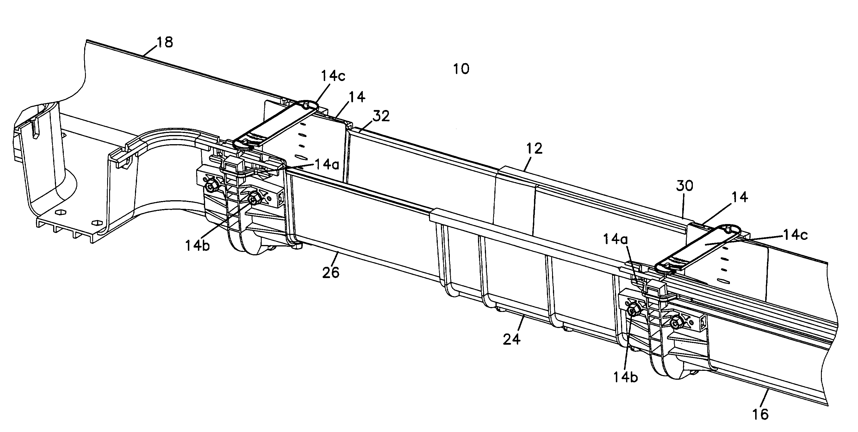
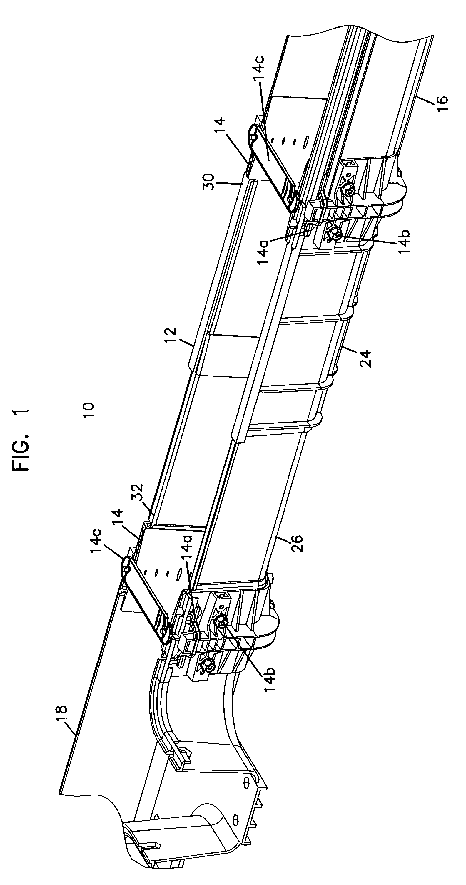
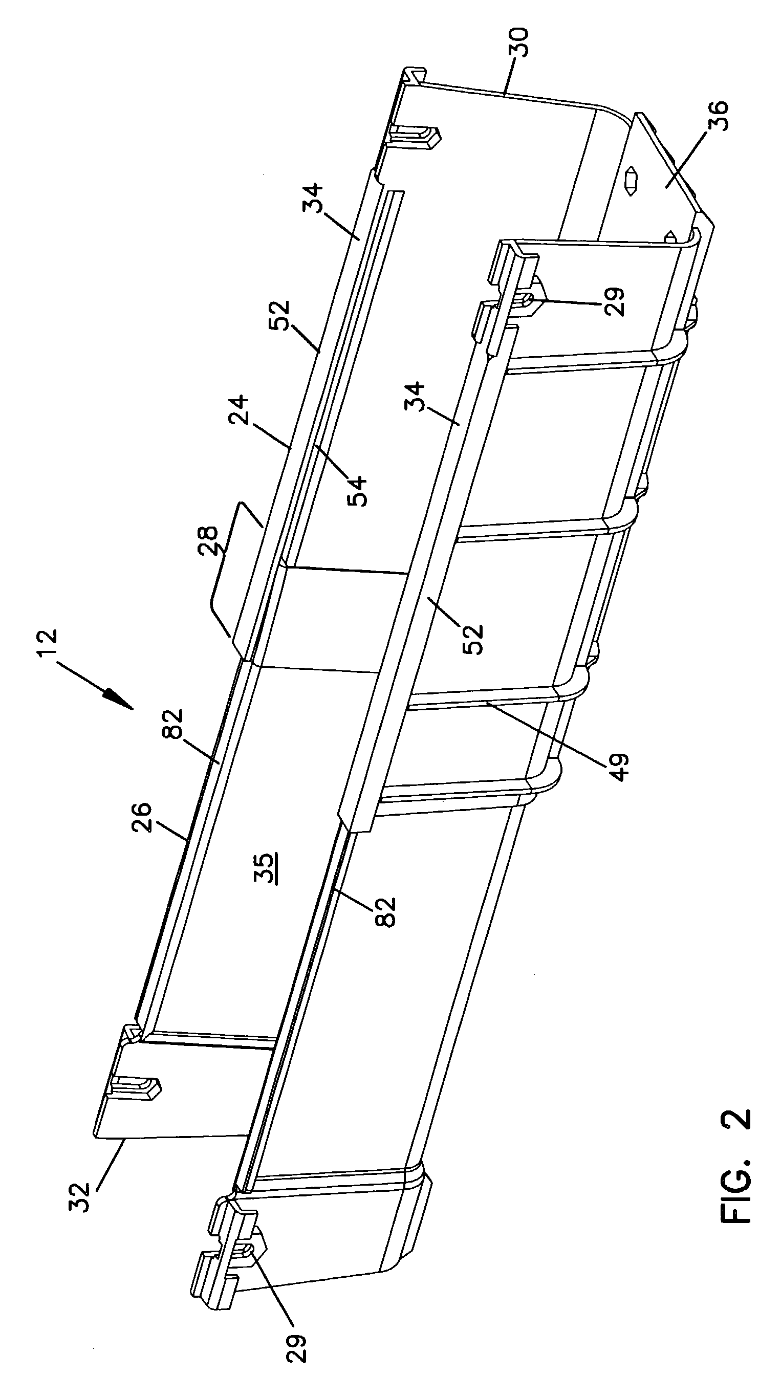
[0027]Referring now to FIG. 1, a cable routing system 10 is shown in accordance with the principals of the present invention. Cable routing system 10 includes a telescoping trough 12 mounted to a coupling 14 on one terminal end 30. Coupling 14 joins telescoping trough 12 to horizontal trough section 16. An opposite terminal end 32 of telescoping trough 12 is mounted to a second coupling 14 which is mounted to a fitting 18 (T-fitting). End 30 can be spaced from end 32 in a telescoping manner.

[0028]Couplings 14 are described in greater detail in U.S. Pat. No. 5,752,781, the disclosure of which is incorporated by reference. Terminal ends 30, 32 are received in generally U-shaped channels in couplings 14. Resilient tabs 14a engage holes 29 in terminal ends 30,32. Fasteners 14b of coupling 14 are screwed down to secure couplings 14 to trough 12. Cable retention members 14c are added to help retain the cables in the various trough and fitting components. Additional couplings, troughs and ...


PUM

PropertyMeasurementUnit
lengthaaaaaaaaaa
areaaaaaaaaaaa
areasaaaaaaaaaa

Abstract

A telescoping cable trough section is provided including first and second U-shaped trough sections which are slideably received with each other. One trough section includes slots, and the other includes flanges received in the slots for mating the two trough sections together to form the telescoping cable trough section.

Description

CROSS REFERENCE TO RELATED APPLICATIONS[0001]This application is a divisional of application Ser. No. 09 / 578,300, filed May 25, 2000, which application is incorporated herein by reference now U.S. Pat. No. 6,739,795.FIELD OF THE INVENTION[0002]This application relates to a system for the management and routing of optical fiber cables and other telecommunications cables. Particularly, this application relates to a trough member for use with other troughs, couplings, and fittings.BACKGROUND OF THE INVENTION[0003]In the telecommunications industry, the use of optical fibers for signal transmissions is accelerating. With the increased utilization of optical fiber systems, optical fiber cable management requires industry attention.[0004]One area of optical fiber management that is necessary is the routing of optical fibers from one piece of equipment to another. For example, in a telecommunications facility, optical fiber cables may be routed between fiber distribution equipment and opti...

Claims


Application Information

Patent Timeline
Patent Type & Authority Patents(United States)
IPC IPC(8): B21D47/00F16L3/00F16L27/00G02B6/44H02G9/04
CPCG02B6/4459H02G9/04Y10T403/7043Y10T29/4984Y10T29/49904Y10T403/7117Y10T29/49623
Inventor HAATAJA, TIMOTHY JONJOHNSON, BRIAN L.JOHNSON, WAYNE ALBINKAMPF, THOMAS WALTER
Owner COMMSCOPE TECH LLC
Why Eureka
Try Eureka