Lighting apparatus, lens and method of making the lens

a technology of light source and lens, which is applied in the field of light source, can solve the problems of difficult to keep the light intensity at the hv point below the permitted limit value, and achieve the effect of improving the light intensity and reducing the difficulty of lighting up

Inactive Publication Date: 2008-06-17
SCHOTT AG
View PDF17 Cites 19 Cited by
  • Summary
  • Abstract
  • Description
  • Claims
  • Application Information

AI Technical Summary

Benefits of technology

[0011]It is an object of the present invention to provide a lighting apparatus and / or a lens suitable for it, which guarantees that the light intensity is as low as possible at the HV point.

Problems solved by technology

Up to now it has proven to be very difficult to keep the light intensity at the HV point below the permitted limiting value while maintaining all the remaining test standards.

Method used


Image

  • Lighting apparatus, lens and method of making the lens
  • Lighting apparatus, lens and method of making the lens
  • Lighting apparatus, lens and method of making the lens

Examples


Embodiment Construction

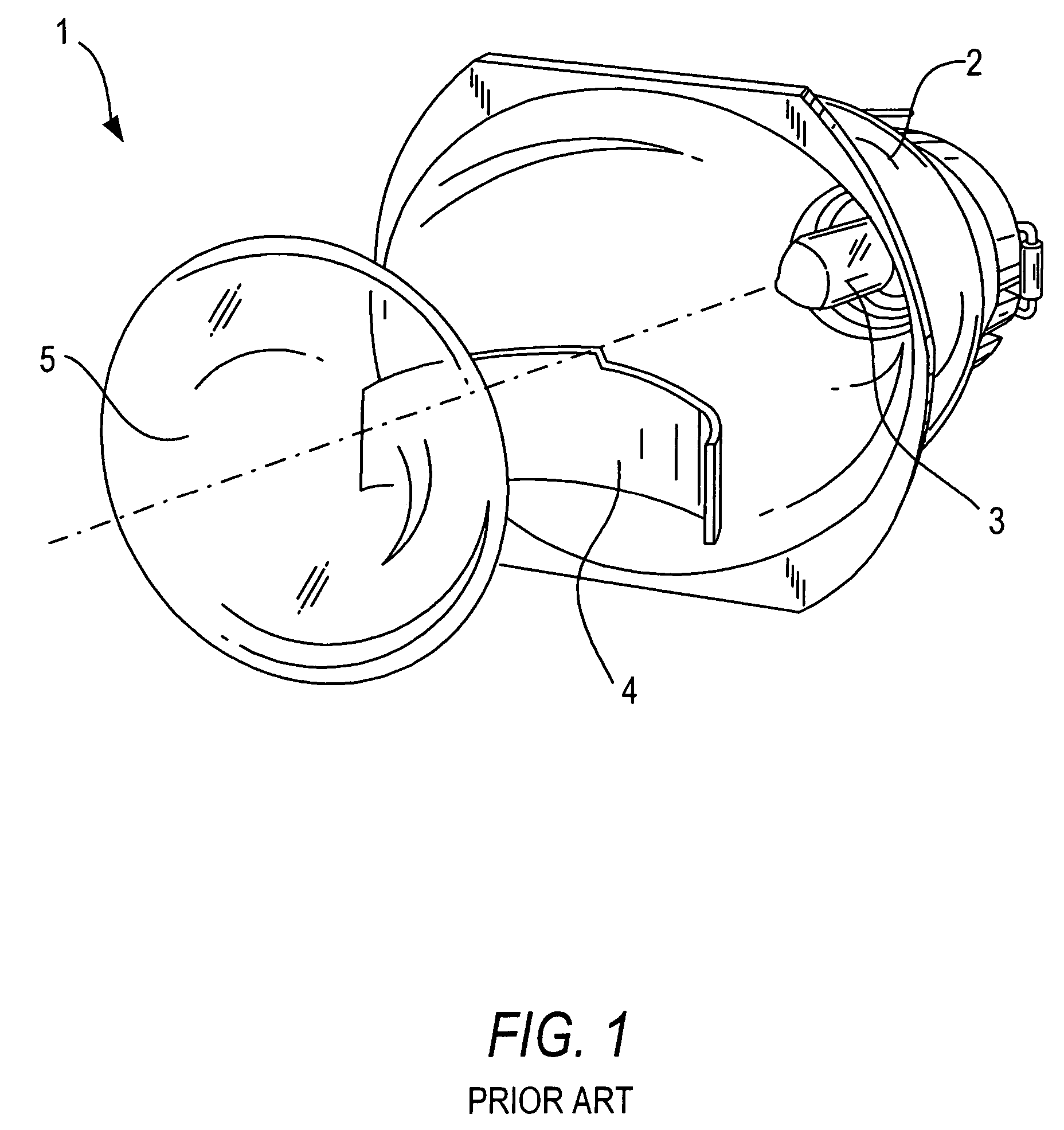
[0035]FIG. 1 shows the main structure of a DE headlight as it is known in the art. The DE headlight 1 comprises a poly-ellipsoidal reflector 2, a halogen light source 3, a diaphragm 4 and a lens 5. The diaphragm 4 is arranged in the path of the light rays between the halogen light source 3 and the lens 5. The usually used diaphragm 4 blocks the lower half of the light beam, so that the headlight lights the ground sooner or closer after passing through the lens. The light beam is deflected down especially toward the right side in order to blind the driver of an oncoming vehicle as little as possible by building a step into the upper edge of the diaphragm 4.

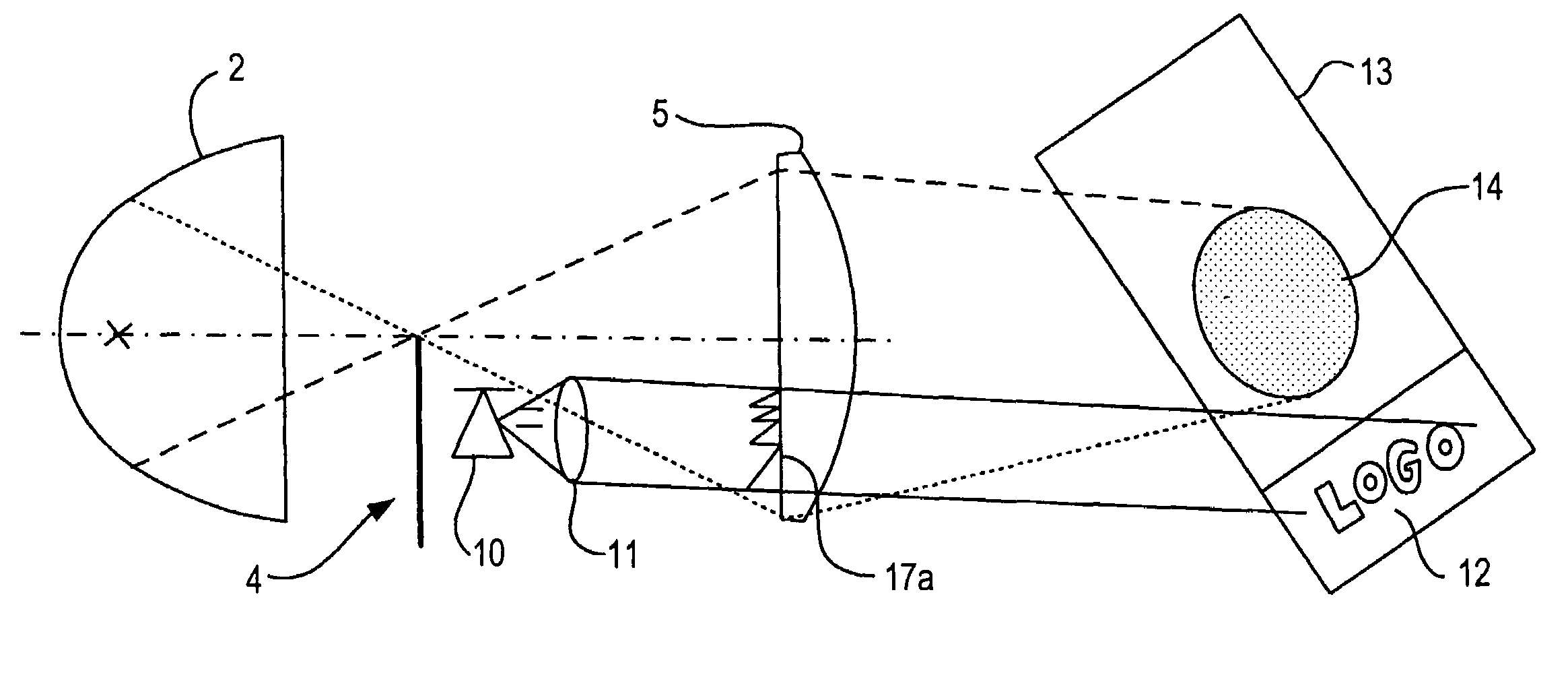
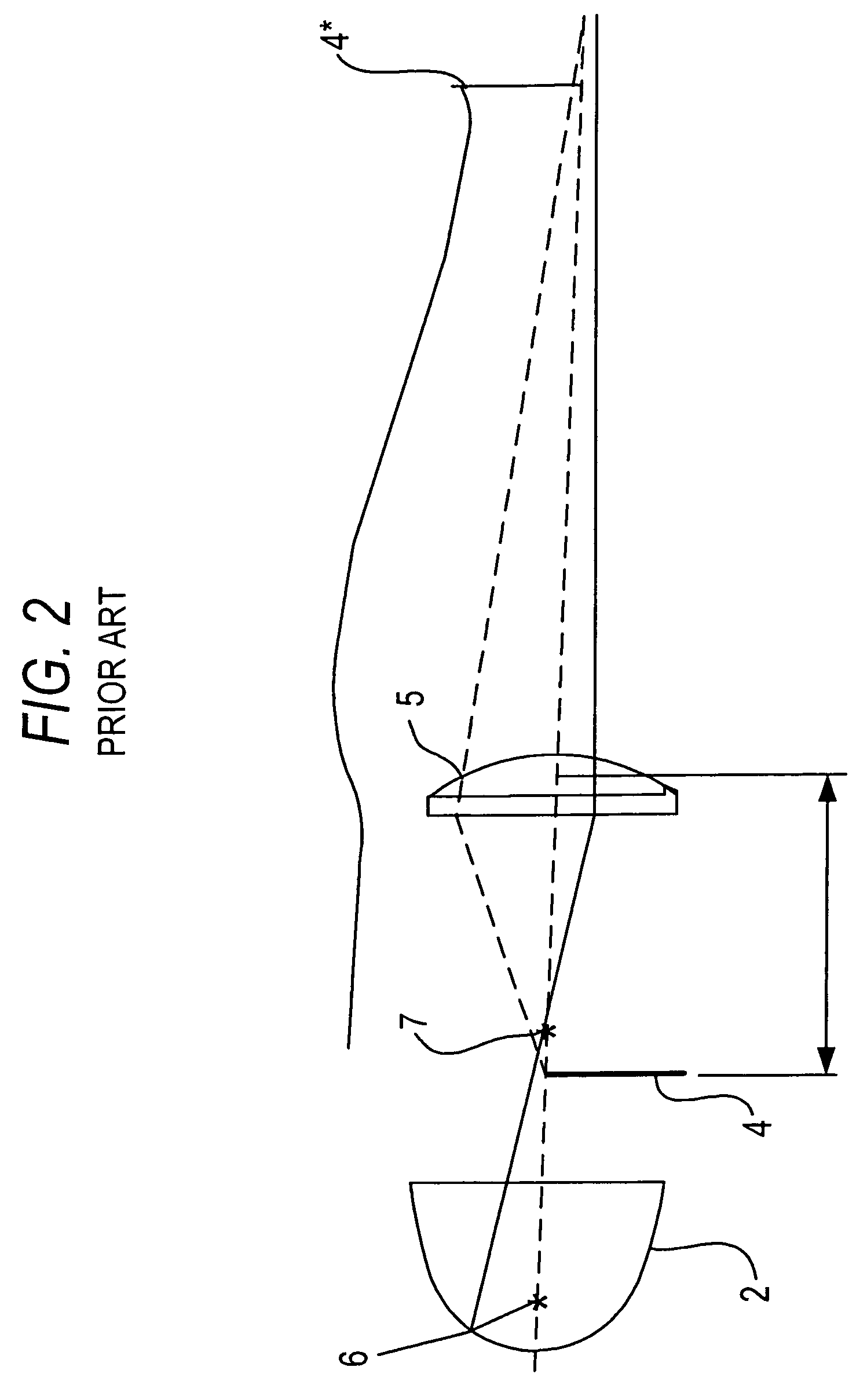
[0036]Light rays in a DE headlight are shown in FIG. 2. A light source is mounted in a reflector 2 at a first focal point 6. The light is focused at a second focal point 7, which is shortly downstream of the diaphragm 4, because of the ellipsoidal shape of the reflector. After that the individual light rays pass through the lens 5 ...


PUM


Abstract

In order to meet the legal requirements regarding color of light from a headlight, especially at the light-dark boundary and how much scattered light can occur in the dark region, a lens (5) is provided, which has a diffractive structure on at least one of its surfaces (8). This lens (5) is built into a headlight with a diaphragm (4) arranged between the lens (5) and a light source (3) so that the diffractive structure is arranged substantially only in a region of the lens surface that is not masked by the diaphragm. In various embodiments a computer-generated hologram (17a-17e) can be arranged in the other region of the lens surface that is masked by the diaphragm, so that the lighting apparatus can perform other functions, such as improving driver visibility, displaying an image, measuring the distance to an object or detecting rain or snow.

Description

BACKGROUND OF THE INVENTION[0001]1. Field of the Invention[0002]The present invention relates to a lighting apparatus, especially for the automotive field, which comprises a light source, a lens having a diffractive structure on at least one of its surfaces and a diaphragm arranged between the light source and the lens. Furthermore the invention also relates to a lens of this type for the above-described lighting device and to a method of making this lens.[0003]2. Description of the Related Art[0004]A lighting apparatus is described in DE 42 15 584 A1, which has a light source, a reflector and a light disk. A diffraction grating is arranged between the light source and the light disk, through which the light reflected from the reflector and originating from light source travels. The diffraction grating has regions with micro-prisms as diffraction elements, through which light aimed in a certain direction is diffracted or deflected. The diffraction-optic elements are formed as scatte...

Claims


Application Information

Patent Timeline
Patent Type & Authority Patents(United States)
IPC IPC(8): G01B13/18B60Q1/00G02B27/44F21S8/12F21S8/10F21V5/00F21V11/16F21V13/00F21W101/10F21Y101/00G02B5/02
CPCF21S48/1233F21S48/1258F21S48/1283F21V5/002G02B5/0252B60Q2400/50F21S48/145F21S41/255F21S41/275F21S41/28F21S41/43G03H1/2202F21S41/20F21W2102/00
Inventor BRINKMANN, MATTHIASPAWLOWSKI, EDGARBEIER, WOLFRAMHARMGARDT, ROLF
Owner SCHOTT AG
Why Eureka
Try Eureka