Portable clean molding apparatus and method of use

a technology of portable clean environment and molding apparatus, which is applied in the field of clean environment, can solve the problems of production scheduling problems, inability to maintain, and the cost of temporary and portable clean environment operation is relatively high, and achieves the effect of improving production efficiency and reducing production costs

Inactive Publication Date: 2008-07-01
KRIPPNER GERRY R
View PDF22 Cites 39 Cited by
  • Summary
  • Abstract
  • Description
  • Claims
  • Application Information

AI Technical Summary

Benefits of technology

[0022]Aspects of the present invention teach certain benefits in construc

Problems solved by technology

However, it is generally costly to maintain such a clean room, much less a lower particulate count permanent environment on the order of class 100, and the molder is often also then limited to the particular mold machine that is installed within the clean room, creating potential problems in production scheduling

Method used


Image

  • Portable clean molding apparatus and method of use
  • Portable clean molding apparatus and method of use
  • Portable clean molding apparatus and method of use

Examples


Embodiment Construction

[0035]The above described drawing figures illustrate aspects of the invention in at least one of its exemplary embodiments, which are further defined in detail in the following description.

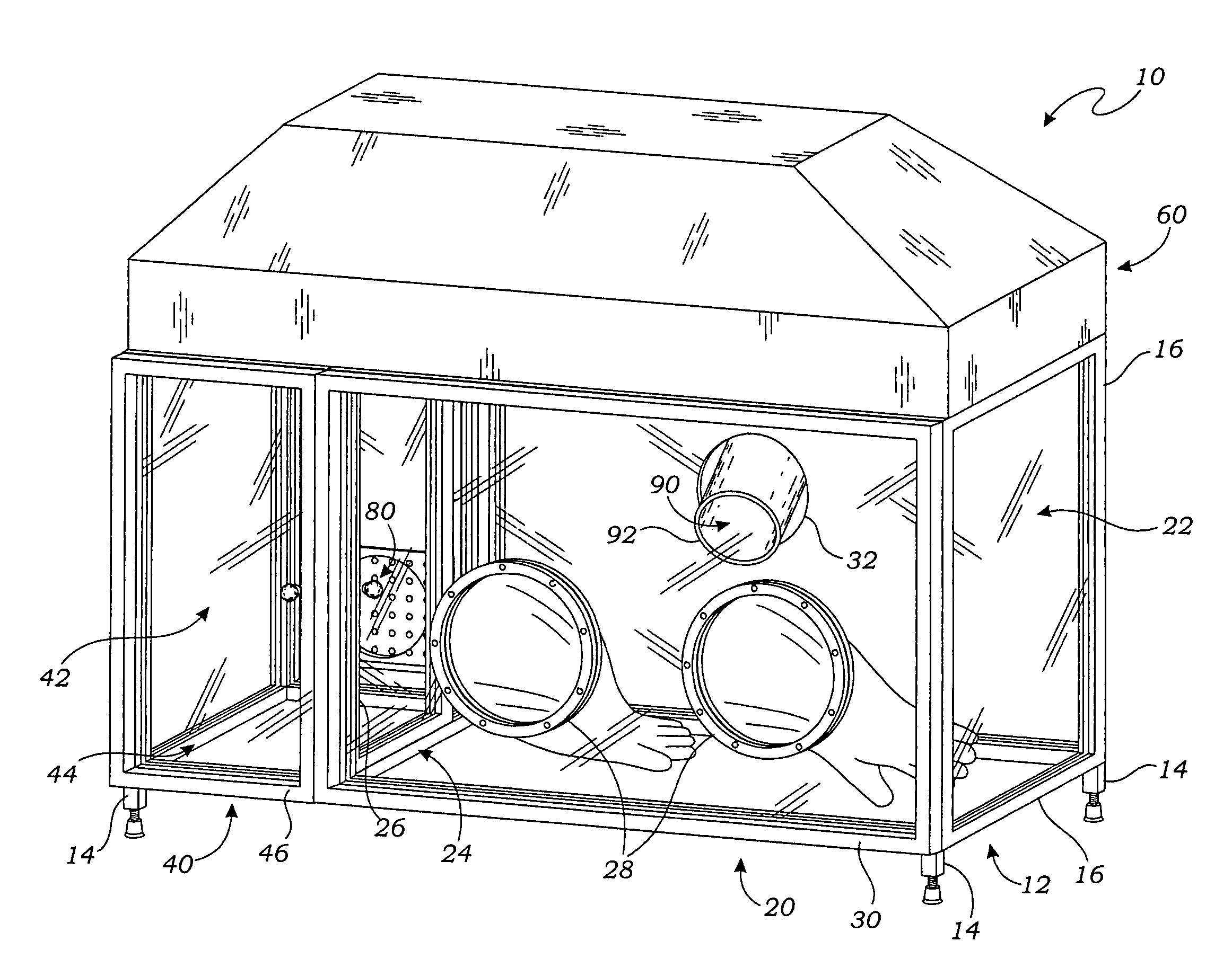
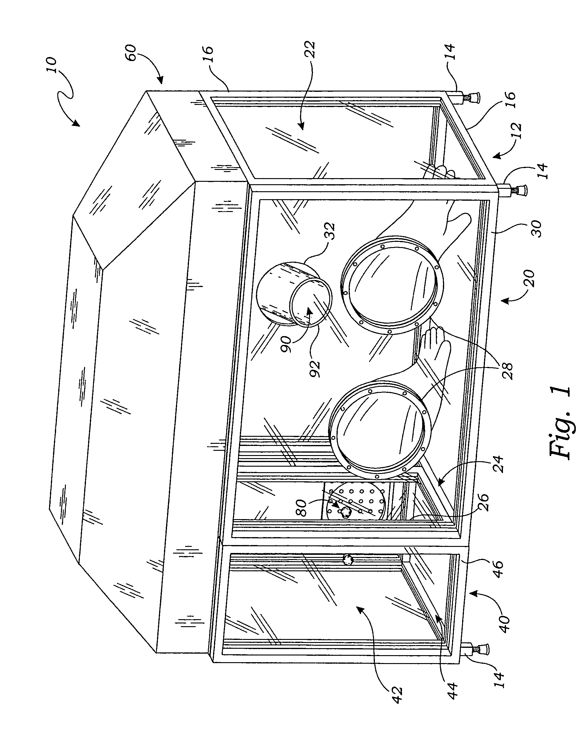
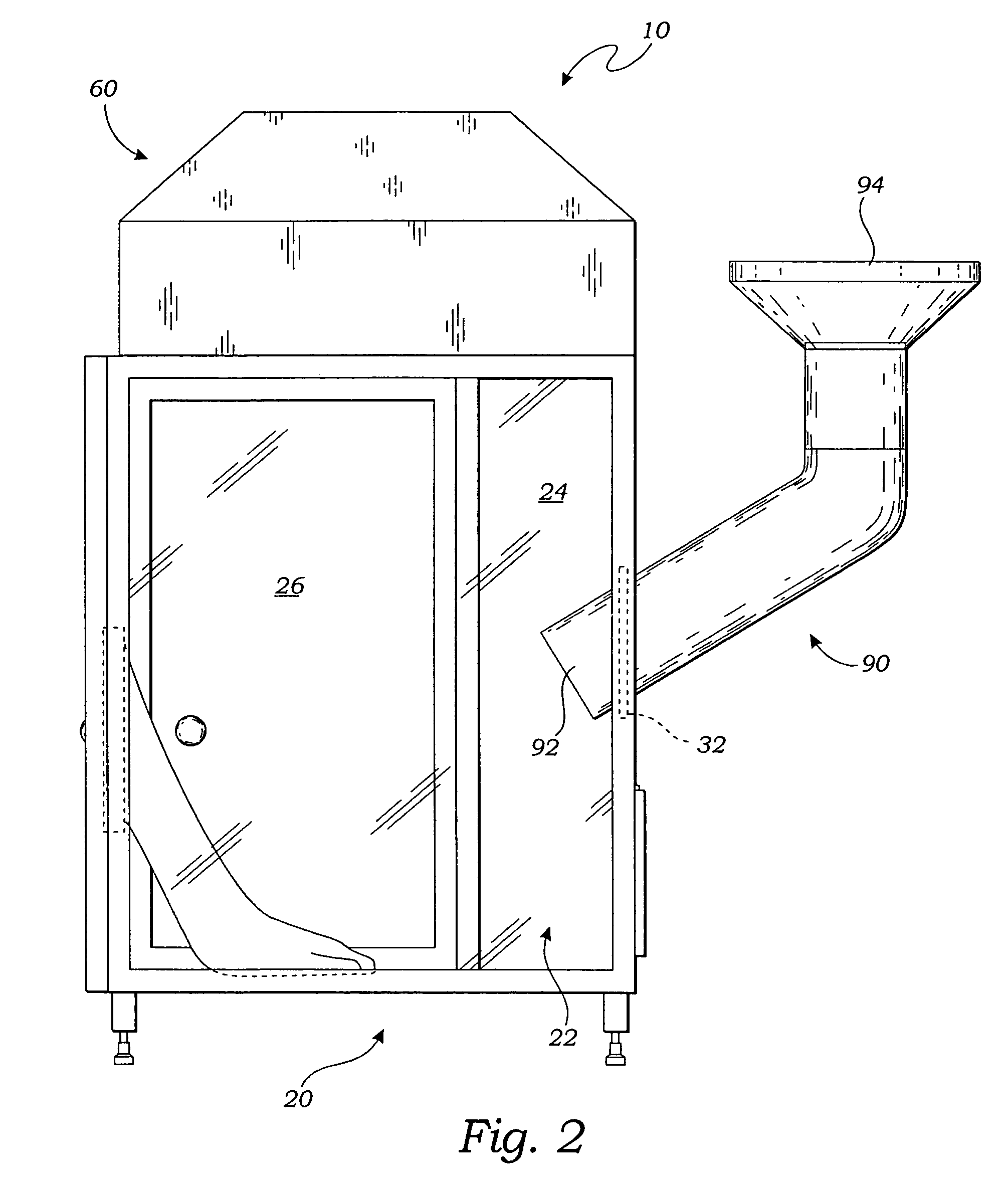
[0036]The present invention is directed to a portable clean molding apparatus 10 for receipt of molded articles 110 ejected from a mold machine 100. The apparatus 10, which is located generally adjacent to the mold machine 100, comprises a receiving chamber 20 having a first interior space 22 and a first side 24 including a selectively openable first door 26; a secondary chamber 40 joined to the receiving chamber 20 substantially along the first side 24 and having a second interior space 42 and a second side 44 including a selectively openable second door 46; an air filtration cover unit 60 installed over the receiving and secondary chambers 20, 40 so as to provide a low-particulate, positive airflow 70 into the first and second interior spaces 22, 42; at least one vent 80 intersecting the seconda...


PUM

PropertyMeasurementUnit
Fractionaaaaaaaaaa
Fractionaaaaaaaaaa
Sizeaaaaaaaaaa

Abstract

A portable clean molding apparatus for receipt of molded articles ejected from a mold machine. The apparatus includes a receiving chamber having a first interior space and a selectively openable first door, a secondary chamber joined to the receiving chamber and having a second interior space and a selectively openable second door, and an air filtration cover unit installed over the receiving and secondary chambers so as to provide a low-particulate, positive airflow into the first and second interior spaces. The apparatus further includes at least one vent communicating with the second interior space so as to allow the airflow to exit the secondary chamber and at least one chute communicating with the first interior space so as to allow the airflow to exit the receiving chamber, the chute being located adjacent to the mold machine for the transfer of molded articles to the receiving chamber.

Description

INCORPORATION BY REFERENCE[0001]Applicants hereby incorporate herein by reference any and all U.S. patents and U.S. patent applications cited or referred to in this application.BACKGROUND OF THE INVENTION[0002]1. Field of the Invention[0003]An aspect of this invention relates generally to clean environments, and more particularly to portable clean environments employed in the field of molding.[0004]2. Description of Related Art[0005]In the molding field, it is often desirable to mold parts in a low particulate count environment. This is particularly true for medical and optical molded parts, for example. Typically, such low particulate count molding is accomplished by locating the entire mold machine within a clean environment, such as a class 100,000 clean room. However, it is generally costly to maintain such a clean room, much less a lower particulate count permanent environment on the order of class 100, and the molder is often also then limited to the particular mold machine th...

Claims


Application Information

Patent Timeline
IPC IPC(8): B03C1/02B03C3/016
CPCB29C45/1701B29C45/1769
Inventor KRIPPNER, GERRY R.GAFFNEY, DEAN F.
Owner KRIPPNER GERRY R
Why Eureka
Try Eureka