
Upright trowel

a technology of upright trowels and trolls, which is applied in the field of upright trowels, can solve the problems of inability to be easily manipulated by the operator with enough precision to allow suitable adhesive coverage, over-bulky upright trowels, and difficult transportation and storage, and achieves the effect of easy and accurate manipulation by the operator

Inactive Publication Date: 2008-07-08
BENO J GUNDLACH
View PDF30 Cites 7 Cited by
  • Summary
  • Abstract
  • Description
  • Claims
  • Application Information

AI Technical Summary

Benefits of technology

[0008]It has been recognized that it would be advantageous to develop an upright trowel that can be easily and accurately manipulated by an operator while in an upright position, and that includes operable components which are protected from damage and contamination.
[0009]The invention provides a trowel device for use by an operator in an upright position, including a trowel blade receiving assembly and a first elongate handle section, operably coupled to and extending away from the blade receiving assembly toward a proximal end of the device. A second elongate handle section can be rotatably fixable with respect to the first elongate handle section and can extend away from the blade receiving assembly toward the proximal end of the device. The first handle section can be rotatable with respect to the second handle section about a longitudinal axis common to each of the handle sections to allow the operator to adjust an angle of a trowel blade of the trowel blade receiving assembly while the operator is an upright position.
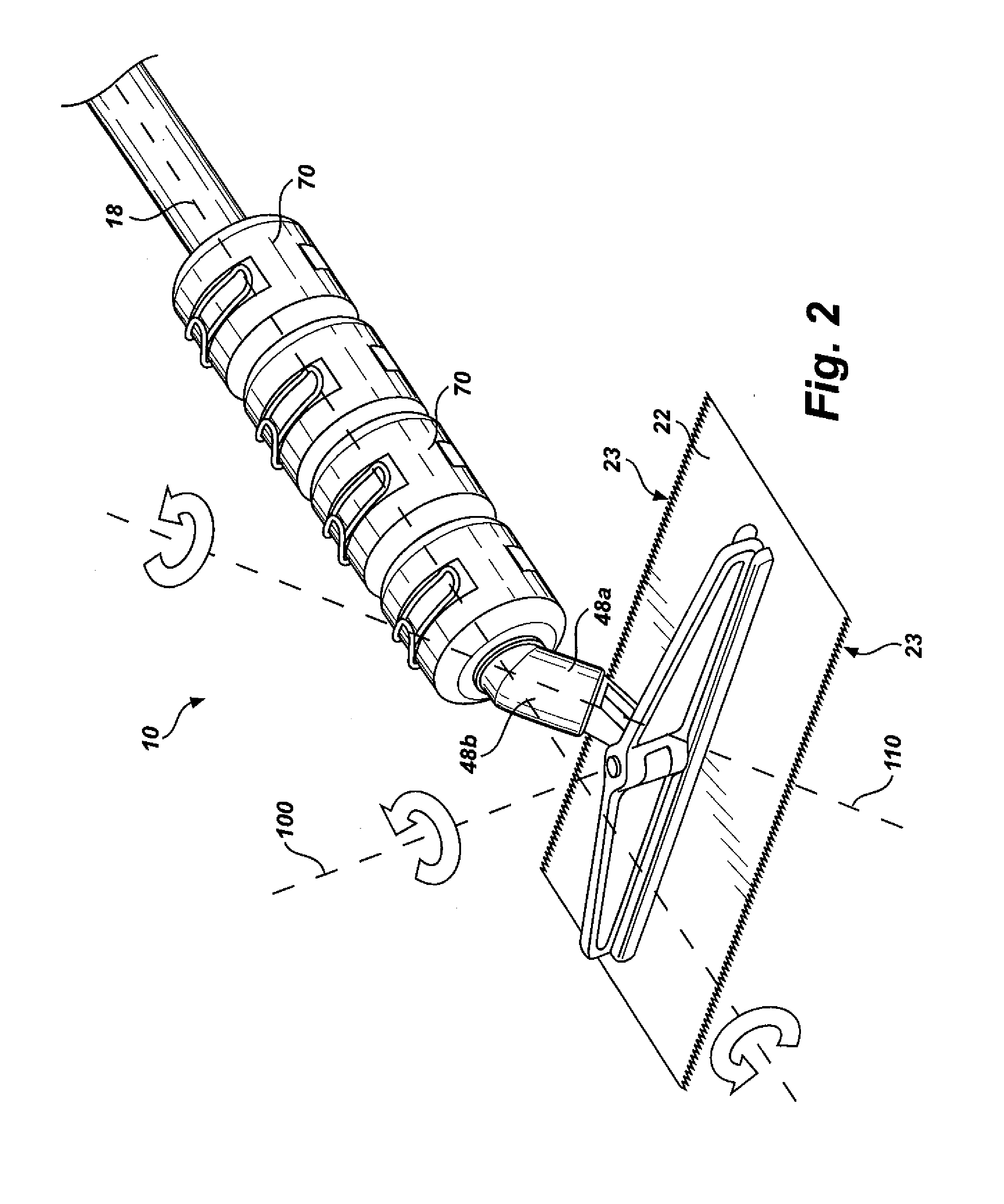
[0010]In accordance with another aspect of the invention, a trowel device for use by an operator in an upright position is provided, including a trowel blade receiving assembly and an elongate handle section, extending away from the blade receiving assembly toward a proximal end of the device. A flexible joint can be operatively coupled between the elongate handle section and the trowel blade receiving assembly. The flexible joint can provide rotatability to the trowel blade receiving assembly about an axis of rotation disposed at an angle to an axis of the elongate handle section. A joint enclosure can at least partially enclose the flexible joint. The joint enclosure can be configured to contain the joint to allow the joint to rotate within the enclosure while protecting the joint from contact with adverse materials.
[0011]In accordance with another aspect of the invention, a method of spreading flooring material from an upright position is provided, including: engaging flooring material disposed on a flooring surface with a trowel blade coupled to an upright trowel device; grasping a first elongate handle section of the upright trowel device to thereby control an angle between a handle of the trowel device and the flooring surface; and grasping and rotating a second elongate handle section of the upright trowel device to thereby alter a relative angle between the trowel blade and the handle of the trowel blade device. The first and second elongate handle sections can be rotatable with respect to one another about a common longitudinal axis to allow rotation of the trowel blade by an operator in an upright position.

Problems solved by technology

The physical toll taken on the knees, legs and backs of operators from kneeling while spreading adhesive can result in significant discomfort during the adhesive application process and / or in significant injury resulting therefrom.
While such upright trowels have addressed some of the problems discussed above, they have proved unsuccessful in that merely adding an elongate handle to an ordinary hand trowel results in a trowel that cannot be manipulated by the operator with enough precision to allow suitable coverage of the adhesive.
However, such attempts have resulted in upright trowels that are overly bulky and difficult to transport and store.
In addition, such conventional upright trowels generally include components that are easily damaged when transported or stored in utility vehicles, and that can become easily fouled with adhesive materials during the adhesive application process.

Method used


Image

  • Upright trowel
  • Upright trowel
  • Upright trowel

Examples


Embodiment Construction

[0021]Reference will now be made to the exemplary embodiments illustrated in the drawings, and specific language will be used herein to describe the same. It will nevertheless be understood that no limitation of the scope of the invention is thereby intended. Alterations and further modifications of the inventive features illustrated herein, and additional applications of the principles of the inventions as illustrated herein, which would occur to one skilled in the relevant art and having possession of this disclosure, are to be considered within the scope of the invention.

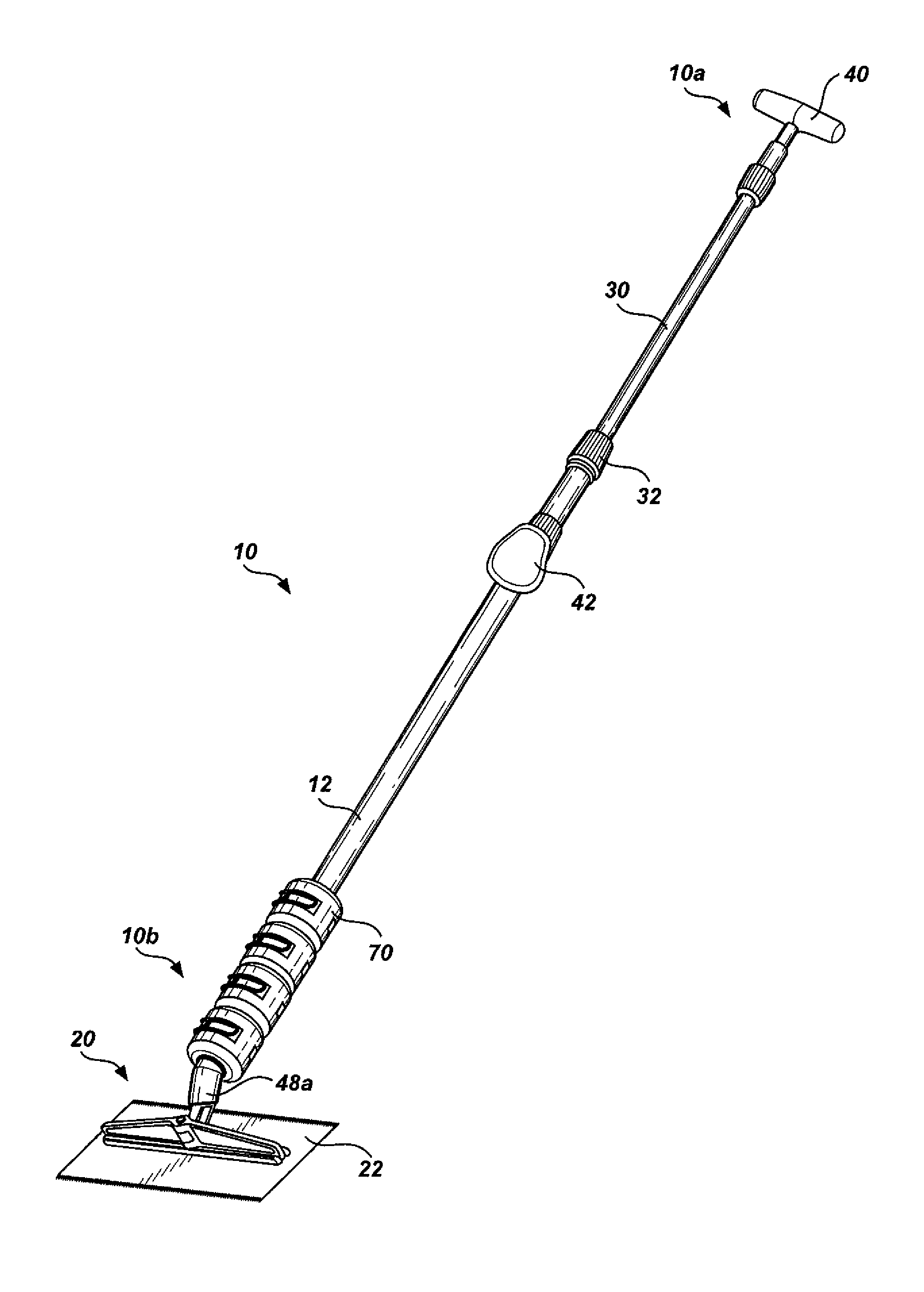
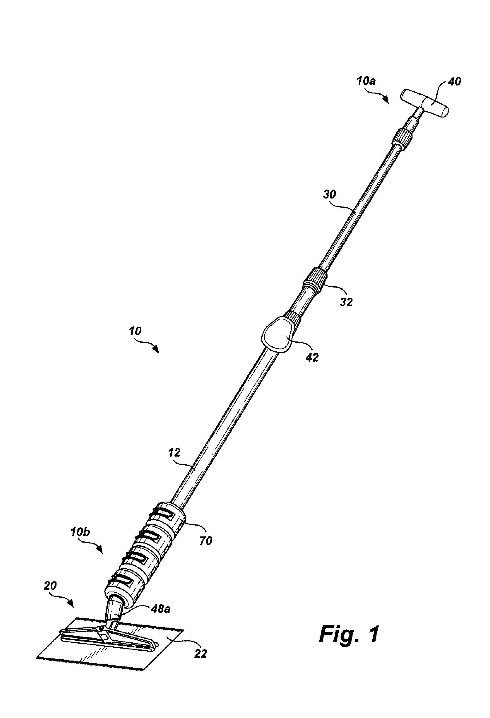
[0022]As illustrated in FIG. 1, a system, indicated generally at 10, in accordance with the present invention is provided for an upright trowel device. The trowel device (hereinafter sometimes referred to as “the trowel”) can be used in a variety of flooring applications and is particularly well suited for applying adhesive or other floor treating compounds to a flooring surface while the operator (not shown) mai...


PUM


Abstract

A trowel device for use by an operator in an upright position comprises a trowel blade receiving assembly and a first elongate handle section, operably coupled to and extending away from the blade receiving assembly toward a proximal end of the device. A second elongate handle section is rotatably fixable with respect to the first elongate handle section and extends away from the blade receiving assembly toward the proximal end of the device. The first handle section is rotatable with respect to the second handle section about a longitudinal axis common to each of the handle sections to allow the operator to adjust an angle of a trowel blade of the trowel blade receiving assembly while the operator is an upright position.

Description

[0001]Priority is claimed of copending U.S. Provisional Patent Application Ser. No. 60 / 647,651, filed Jan. 26, 2005, which is hereby incorporated herein in its entirety.BACKGROUND OF THE INVENTION[0002]1. Field of the Invention[0003]The present invention relates generally to trowels for use in flooring installation. More particularly, the present invention relates to trowels that are used by an operator while the operator is in a generally upright orientation.[0004]2. Related Art[0005]Installation of flooring materials, such as vinyl flooring and some types of carpeting, often requires application of adhesive material to the floor area over which the flooring is to be installed. Adhesive materials are most often applied by heaping a large portion of adhesive in a central location and spreading the adhesive outwardly with a hand trowel that includes toothed depressions through which the adhesive passes to ensure consistent coverage of the adhesive. Hand trowels generally require that...

Claims


Application Information

Patent Timeline
IPC IPC(8): E01C19/24
CPCA47G27/0487B25G1/04E04F21/20B25G1/06Y10T16/44
Inventor MEYERS, LAWRENCE G.
Owner BENO J GUNDLACH
Learn More