High current switch and method of operation

a high-current switch and high-current technology, applied in the direction of high-tension/heavy-dress switches, contacts, air-break switches, etc., can solve the problems of large manufacturing size and complexity, the perceived risk of scheduling the entire feeder out of service to pick-up a small spur is very large, and the whole feeder remains out of service. , to achieve the effect of reducing undesirable bending forces on the connection point and reducing bending forces

Inactive Publication Date: 2008-07-08
THOMAS & BETTS INT INC
View PDF19 Cites 23 Cited by
  • Summary
  • Abstract
  • Description
  • Claims
  • Application Information

AI Technical Summary

Benefits of technology

[0012]In a preferred embodiment, the switch further includes a viewing port disposed in the insulative housing wall adjacent the first electrical contact to permit viewing of the first electrical contact within the housing bore. The viewing port preferably includes a transparent element made from a clear insulative plastic material fixed within the housing wall. The transparent element may further be provided with a magnification feature to enhance viewing and the housing wall may include a protruding boss portion having a hole for receiving the transparent element.
[0020]The switch assembly may further include method and apparatus for reducing bending forces on an electrical connection point. More specifically, the feeder contact and current carrying male pin are electrically coupled and include longitudinal axes which are substantially non-parallel. The feeder contact preferably includes a mechanically weakened portion adjacent the electrical connection. Upon closing of the switch, high current flows through the male pine and feeder contact generating electromagnetic bending forces. These bending forces tend to act on the electrical connection thereby loosening or damaging the connection. The mechanically weakened portion directs the bending forces away from the electrical connection to reduce undesirable bending forces on the connection point.

Problems solved by technology

This means that the whole feeder remains out of service or a live end cap must be installed to separate the main feeder from the spur containing the defect.
However, the perceived risk of scheduling the entire feeder out of service to pick-up a small spur is very large, especially during the summer or other high load periods.
One drawback with the circuit interrupter disclosed in the '804 patent is its size and complexity in manufacture.
Another drawback relates to the fact that the position indicator is located at the toggle mechanism away from the switch contacts.
Aside from safety concerns, such arcing causes damage to the contacts and the surrounding housing.
Air insulation chambers are generally very large.
Yet another problem with high current switches described above is related to electromagnetic fields which generate undesirable bending forces.

Method used


Image

  • High current switch and method of operation
  • High current switch and method of operation
  • High current switch and method of operation

Examples


Embodiment Construction

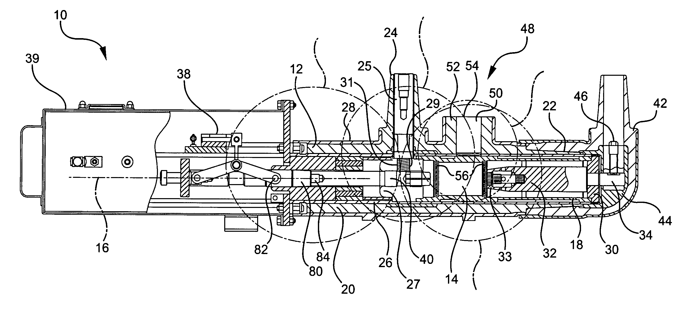
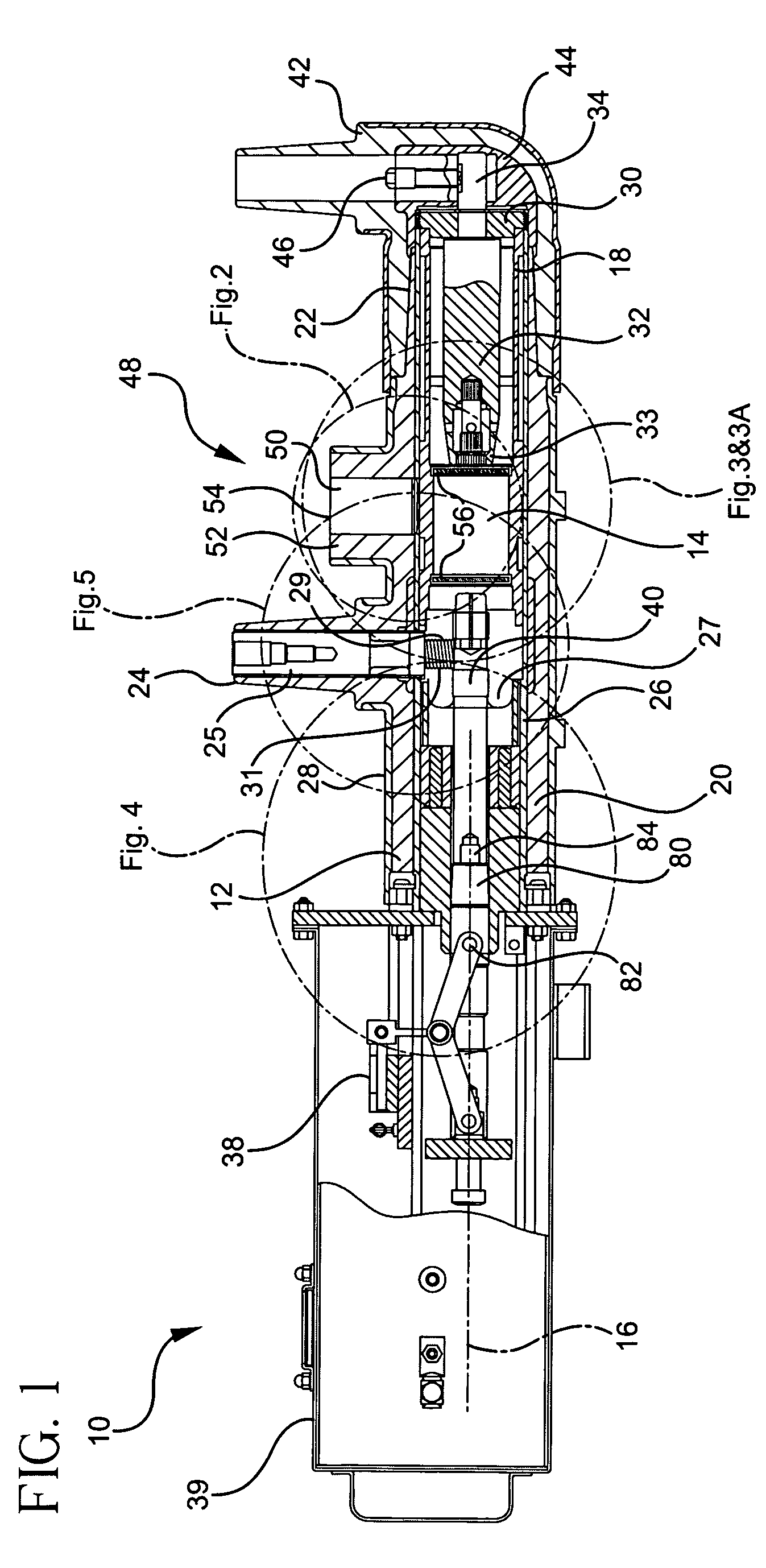
[0028]Referring first to FIG. 1, in a preferred embodiment, the switch 10 according to the preferred embodiment of the present invention is a medium-voltage, one-operation switch. As used in this disclosure with reference to apparatus, the term “medium voltage” means apparatus which is adapted to operate in electric utility power systems, such as in systems operating at nominal voltages of about 5 kv to about 35 kv, commonly referred to as “distribution” systems, as well as equipment for use in “transmission” systems. A high current switch of this type is disclosed in commonly owned U.S. Pat. No. 5,808,258, the disclosure of which is incorporated herein by reference in its entirety.

[0029]The term “one-operation” generally means a device used to temporarily interrupt power between a “feeder” or “source” circuit and a “spur” circuit in order to safely access or effect repairs on the spur circuit. Upon successful repairs of the spur circuit, the switch is closed to restore power to the...


PUM


Abstract

An electrical switch which includes an insulative housing having a wall defining an axial bore therein, a first electrical contact disposed in the housing bore and a second electrical contact movably disposed in the housing bore between an open position and a closed position. When the contacts are in their open position, the second electrical contact is spaced apart from the first electrical contact and when the contacts are in their closed position, the second electrical contact is in electrical contact with the first electrical contact. The switch includes features to enhance safety and operation by reducing the possibility of arcing or flashover before and during the switching operation and to provide of visual indication of the state of the switch.

Description

FIELD OF THE INVENTION[0001]The present invention relates generally to high current switches used in electric power distribution systems and, more particularly, to an electrically insulated, deadfront, single operation, medium voltage, high current closing device.BACKGROUND OF THE INVENTION[0002]An urban utility experiences approximately 1,500 failures on its network feeders each year. Each feeder outage duration is directly proportional to the risk of customer interruption and the stress experienced by other feeders and transformers in the network. The defective component must remain out of service during repair and / or replacement. This means that the whole feeder remains out of service or a live end cap must be installed to separate the main feeder from the spur containing the defect. If a live end cap is installed, the feeder must be de-energized a second time to reconnect the required spur. This second outage is usually scheduled as soon as possible to restore the system to norm...

Claims


Application Information

Patent Timeline
Patent Type & Authority Patents(United States)
IPC IPC(8): H01H33/00
CPCH01H33/02H01H1/385H01H31/32H01H2009/0292H01H33/565H01H2003/0273H01H33/025
Inventor STEPNIAK, FRANKSIEBENS, LARRYBINDICS, CHARLESREED, ANTHONY
Owner THOMAS & BETTS INT INC
Why Eureka
Try Eureka