Flexible sleeve liner for a convolute duct

a flexible, convoluted technology, applied in the direction of sleeve/socket joint, adjustable joint, mechanical equipment, etc., can solve the problems of reducing the air flow rate, adversely affecting the local air flow, and restricting the air flow, so as to avoid the inherent frictional pressure loss

Inactive Publication Date: 2008-07-15
GM GLOBAL TECH OPERATIONS LLC
View PDF16 Cites 37 Cited by
  • Summary
  • Abstract
  • Description
  • Claims
  • Application Information

AI Technical Summary

Benefits of technology

[0021]The present invention is an air induction system for an internal combustion engine of a motor vehicle in which the outlet air assembly includes a sleeved convolute duct whereby the convolute duct performs its essential NVH control, yet avoids the inherent frictional pressure losses associated with conventional convolute ducts.
[0022]The present invention provides a sleeve liner at the inner side of the sidewall of a convolute duct. The sleeve liner provides a laminar air flow therethrough, whereby the air flow avoids any interaction with the ridges and cavities of the convulations, yet further provides duct flexibility. The sleeve liner has a smooth, continuously even inner surface from one end to the other (by “smooth, continuously even inner surface” is meant the inner surface is without convolutes, breaks or other irregularities) providing consistent airflow with little pressure loss, and at the same time, the sleeve liner is adequately flexible to maintain the ability of the convolute duct to flex in response to engine motion, such as compression, extension, twist, off-alignment, etc.
[0024]The sleeve liner provides a convolute duct with a smooth, continuously even internal surface from one end to the other, preferably being of a constant inner diameter, whereby the sleeve liner effectively reduces the pressure loss which would be otherwise caused by convolute wall friction and at the same time minimizes air flow separation, turbulence and swirl. Furthermore, because the sleeve liner has a free end which freely slides in relation to the convolute duct as the convolute duct moves, it can maintain the ability of the convolute to readily flex and twist in response to engine motion and vibration.
[0025]Accordingly, it is an object of the present invention to provide an air induction system for an internal combustion engine of a motor vehicle in which the outlet air assembly includes a sleeved convolute duct, whereby the convolute duct performs its essential NVH control, yet avoids the inherent frictional pressure losses associated with conventional convolute ducts.

Problems solved by technology

Oftentimes, these convolute ducts are of a complicated serpentine configuration due to limited space within the motor vehicle engine compartment.
It is a challenge to keep a proper balance as between all of these needs because many of the requirements are conflicting.
Though convolute ducts 14 are effective in absorbing engine motions and isolating vibrations, a problem with convolute ducts is that the internal circumferential ridges 20 of the convolutes 16 have large surface roughness, and each provide a cavity 22 adversely affecting local air flow.
In particular, highly convolute ducts with compound angles can further restrict air flow, due to large flow turbulence.
However, most importantly, the surface roughness of the convolute duct sidewall has the biggest effect on the friction pressure loss.
In fact, the higher the Reynolds number (Re), the more likely the effects of roughness will be significant.
From Equation 1, reducing convolute height would decrease the wall friction, but this would conflict with the duct flexibility requirement.
Consequently, engine power output is reduced as a result of pressure loss caused by a convolute duct.
Although less convolutes will be able to reduce the air friction resistance, it still has inherent problems.
Consequently, the excessive vibrations from the engine could cause discomfort to drivers and passengers.
Secondly, each convolute has to take more engine positional displacements due to less convolutes.
As a result, the durability of a short convoluted duct is always a significant concern.
Finally, a short convolute duct needs more assembly effort in the vehicle assembly plant.
Commonly, this type of duct can cause human ergonomic issues, thus increasing the assembly cost and time.
Although lowering the pressure loss within the convolute duct, the large diameter convolute duct has several limitations.
If the convolute duct diameter is too large relative these components, the air flow can experience sudden expansion at the exit of the mass air flow sensor and a sudden contraction at the entry of the engine throttle body.
This sudden expansion and contraction of the air flow can cause significant pressure loss.

Method used


Image

  • Flexible sleeve liner for a convolute duct
  • Flexible sleeve liner for a convolute duct
  • Flexible sleeve liner for a convolute duct

Examples


Embodiment Construction

[0038]Referring now to the Drawing, FIGS. 2 through 5B depict various aspects and examples of a sleeve lined convolute duct according to the present invention.

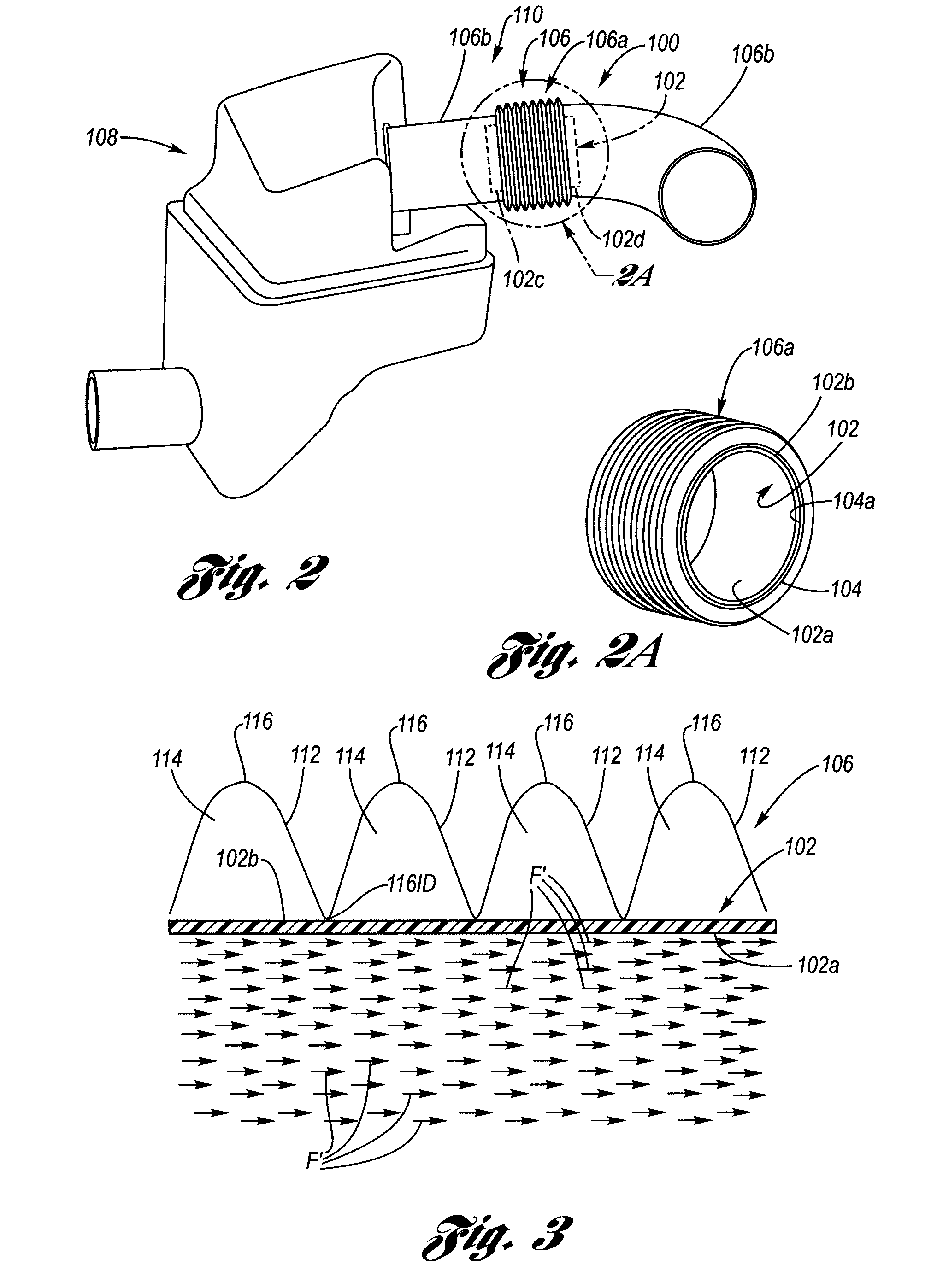
[0039]As shown at FIGS. 2 and 2A, the sleeve-lined convolute duct 100 according to the present invention features a sleeve liner 102 disposed at the inner side 104a of the sidewall 104 of a convolute duct 106. An air induction system (AIS) 108 of an internal combustion engine of a motor vehicle includes, conventionally, an air cleaner with a mass air flow sensor package which is connected to a throttle body of the engine intake manifold (not shown) by an air cleaner outlet duct assembly 110 which includes the sleeve lined convolute duct 100.

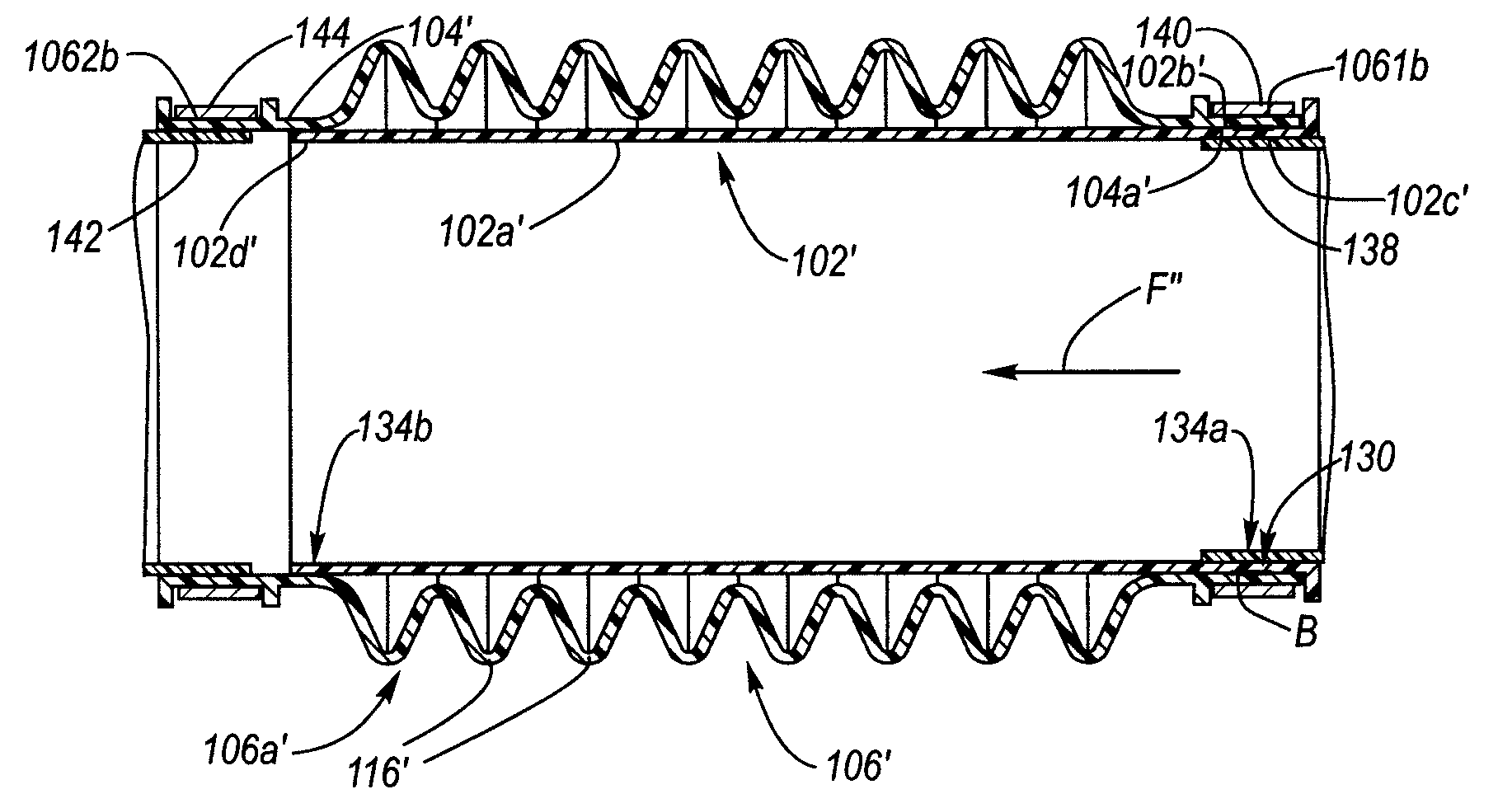
[0040]The sleeve liner 102 has a smooth, continuously even inner surface 102a between its attached and free ends 102c, 102d which provides a laminar air flow F′ therethrough, whereby the air flow avoids any interaction with the ridges 112 and cavities 114 of the convolutes 116 of the convol...


PUM


Abstract

An air induction system wherein the outlet air assembly includes a sleeve-lined convolute duct. A sleeve liner is disposed within a convolute duct which spans the convolutes, wherein an attached end of the sleeve liner is attached to a non-convolute portion of the convolute duct, wherein a free end is freely slidable in the convolute duct, and wherein the free end of the sleeve liner and the attached end of the sleeve liner each serve as a sealing cuff whereby air flow is laminar therethrough irrespective of the convolutes.

Description

TECHNICAL FIELD[0001]The present invention relates to convolute ducts, particularly those used for automotive air induction systems. More particularly, the present invention relates to a flexible sleeve liner for smoothly lining an interior radius of a convolute duct.BACKGROUND OF THE INVENTION[0002]The air induction system (AIS) of an internal combustion engine of a motor vehicle, see generally 10 in FIG. 1, is a complex and finely-tuned system, balancing requirements and constraints that are often in tension with one another.[0003]Conventionally, an air cleaner with a mass air flow sensor package 10a is connected to the engine intake manifold (not shown) by an air cleaner outlet duct assembly 12 which includes a convolute duct 14. Convolute air ducts of various lengths and sizes are used to transfer clean, filtered and metered air from an air filter to the engine air intake manifold. Oftentimes, these convolute ducts are of a complicated serpentine configuration due to limited spa...

Claims


Application Information

Patent Timeline
Patent Type & Authority Patents(United States)
IPC IPC(8): F16L11/00
CPCF16L11/15F16L55/041F16L11/20Y02T10/12
Inventor OSTAN, TERRY W.HUANG, JINLI, LEI
Owner GM GLOBAL TECH OPERATIONS LLC
Why Eureka
Try Eureka