
Dynamic power management in a processor design

a technology of dynamic power management and processor design, applied in the direction of program control, liquid/fluent solid measurement, instruments, etc., can solve the problems of neither software nor hardware power management, and the condition may last for an extended period of tim

Active Publication Date: 2008-07-15
META PLATFORMS INC +1
View PDF12 Cites 22 Cited by
  • Summary
  • Abstract
  • Description
  • Claims
  • Application Information

AI Technical Summary

Problems solved by technology

Stall conditions drive a corresponding pipeline stage into a stall state, and many of these stall conditions may last for an extended period of time.
A challenge found, however, is that when a pipeline stage stalls, the pipeline is still considered an “active” pipeline and, therefore, neither software nor hardware power management gates off the pipeline's clocks.

Method used


Image

  • Dynamic power management in a processor design
  • Dynamic power management in a processor design
  • Dynamic power management in a processor design

Examples


Embodiment Construction

[0022]The following is intended to provide a detailed description of an example of the invention and should not be taken to be limiting of the invention itself. Rather, any number of variations may fall within the scope of the invention, which is defined in the claims following the description.

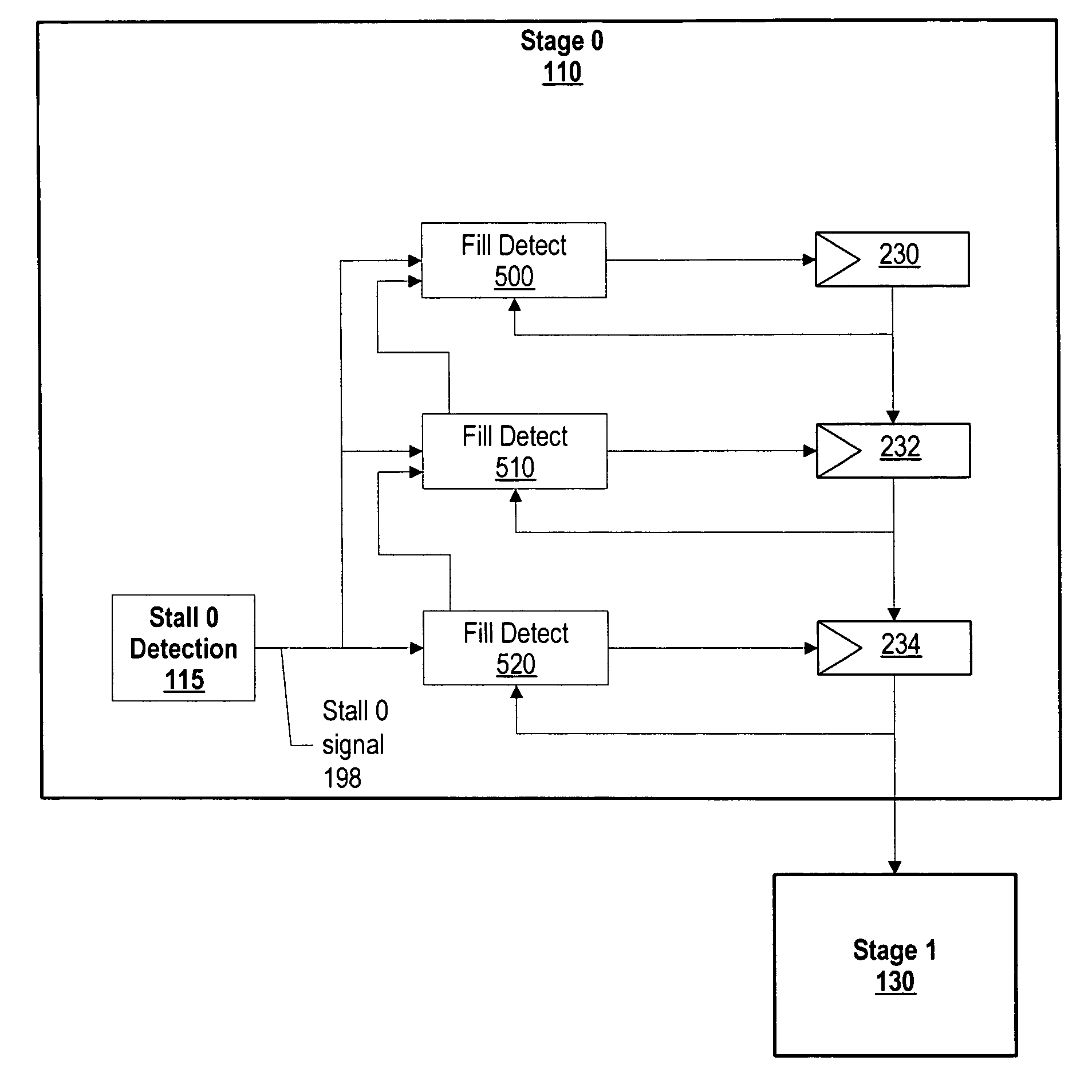
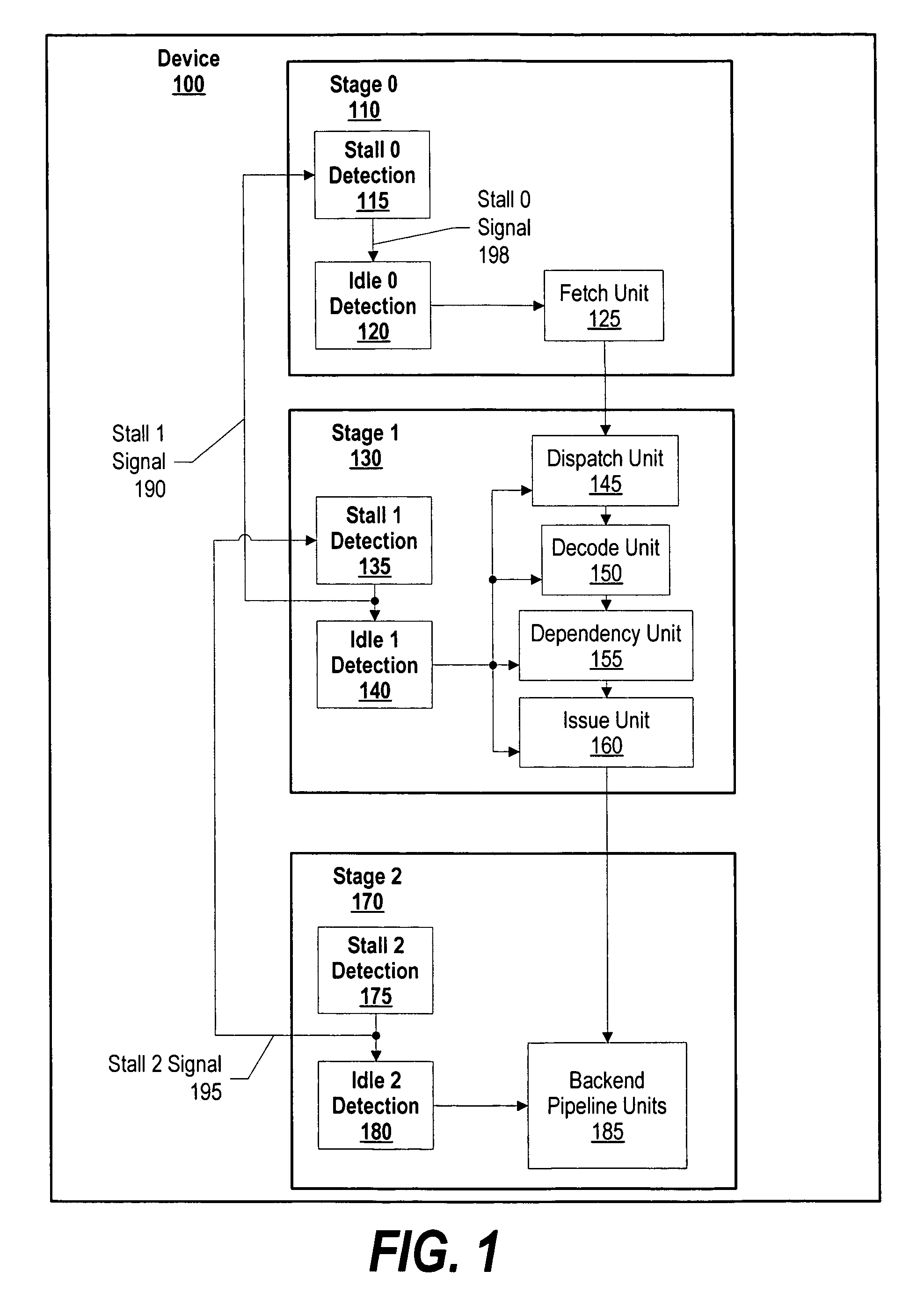
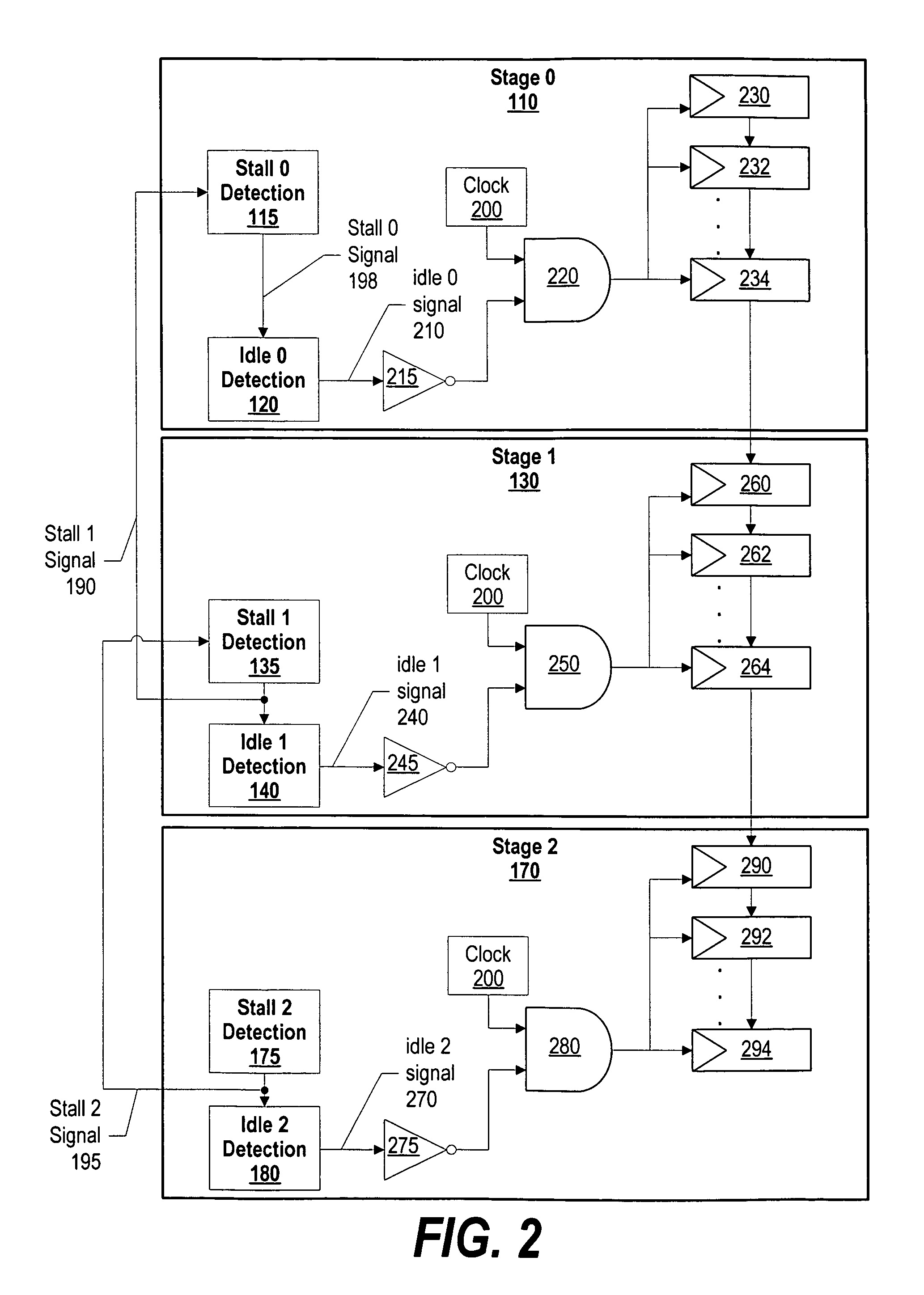
[0023]FIG. 1 is a diagram showing pipeline stages gating off clocks to pipeline units (e.g. instruction units and execution units) and propagating a stall signal to upstream pipeline stages. A designer segments a pipeline into “stages” by including stall and idle detection points at places within the pipeline that detect whether the pipeline is stalled or idle. Device 100 includes stage 0110, stage 1130, and stage 2170. Each stage includes one or more pipeline units, and each pipeline unit includes multiple registers (see FIG. 2 and corresponding text for further details regarding pipeline unit registers).

[0024]Stage 2170 includes stall 2 detection 175, idle 2 detection 180, and backend pipeli...


PUM


Abstract

A pipeline stage's stall detection logic detects a stall condition, and sends a signal to idle detection logic to gate off the pipeline's register clocks. The stall detection logic also monitors a downstream pipeline stage's stall condition, and instructs the idle detection logic to gate off the pipeline stage's registers when the downstream pipeline stage is in a stall condition as well. In addition, when the pipeline stage's stall detection logic detects a stall condition, either from the downstream pipeline stage or from its own pipeline units, the pipeline stage's stall detection logic informs an upstream pipeline stage to gate off its clocks and thus, conserve more power.

Description

BACKGROUND OF THE INVENTION[0001]1. Technical Field[0002]The present invention relates to a system and method for dynamic power management in a processor design. More particularly, the present invention relates to a system and method for using a stall condition to instruct idle detection logic to gate off register clocks within a pipeline stage in order to conserve power.[0003]2. Description of the Related Art[0004]Computer system designs incorporate a multitude of design approaches in order to achieve maximum performance. Once such design approach is pipelining. A pipeline is an implementation technique whereby multiple instructions are overlapped in execution. Pipelines may be segmented into “stages,” whereby each stage includes one or more instruction units or execution units. A pipeline stage includes a “stall point,” which is a location in the pipeline that checks for a stall condition. For example, a pipeline stage may include an issue unit, whereby the issue unit checks for s...

Claims


Application Information

Patent Timeline
Patent Type & Authority Patents(United States)
IPC IPC(8): G06F1/00G06F1/26G06F1/32
CPCG06F1/3228G06F1/3237G06F9/3867G06F1/3243Y02B60/1239Y02B60/1221Y02D10/00
Inventor ABERNATHY, CHRISTOPHER MICHAELDEMENT, JONATHAN JAMESHALL, RONALDPHILHOWER, ROBERT ALANSHIPPY, DAVID
Owner META PLATFORMS INC
Learn More