Power savings and/or dynamic power management in a memory

a power management and memory technology, applied in the field of memory, can solve the problems of limiting the power management capabilities of firmware controlled implementations, insufficient capabilities of existing buffer controllers, and long-term, and achieve the effect of reducing overhead or minimizing overhead

Active Publication Date: 2012-12-25
AVAGO TECH INT SALES PTE LTD
View PDF6 Cites 20 Cited by
  • Summary
  • Abstract
  • Description
  • Claims
  • Application Information

AI Technical Summary

Benefits of technology

[0010]The objects, features and advantages of the present invention include a memory that may (i) provide a power savings feature, (ii) work with the arbiter to eliminate or minimize overhead due to power down, (iii) work seamlessly with existing refresh logic, (iv) allow a power down any time a protocol engine returns to idle and the memory is precharged, (v) be implemented without firmware interaction after initial setup, (vi) allow dynamic power reduction any time that there is not a need for buffer access for a few clocks or longer, (vii) be transparent to a user and / or firmware and / or (viii) work automatically with existing refresh logic.

Problems solved by technology

Conventional memory controllers generally limit power management capabilities to firmware controlled implementations.
Such approaches only allow deep, long-term, power reduction modes to be used given the relative slowness of the processor compared to the fast nature of the memory controller.
Given the ever increasing need for power reduction, the capabilities of existing buffer controllers are inadequate, leaving a significant potential for power reduction untapped.
Such implementations only work for longer, planned periods of inactivity.
However, the JEDEC specified feature only deals with the memory, not how a controller should implement support for this feature (apart from the implication that the controller must meet whatever timing requirements are set out in the JEDEC standard).
Existing power management solutions only operate when activity is completely suspended.

Method used


Image

  • Power savings and/or dynamic power management in a memory
  • Power savings and/or dynamic power management in a memory
  • Power savings and/or dynamic power management in a memory

Examples


Embodiment Construction

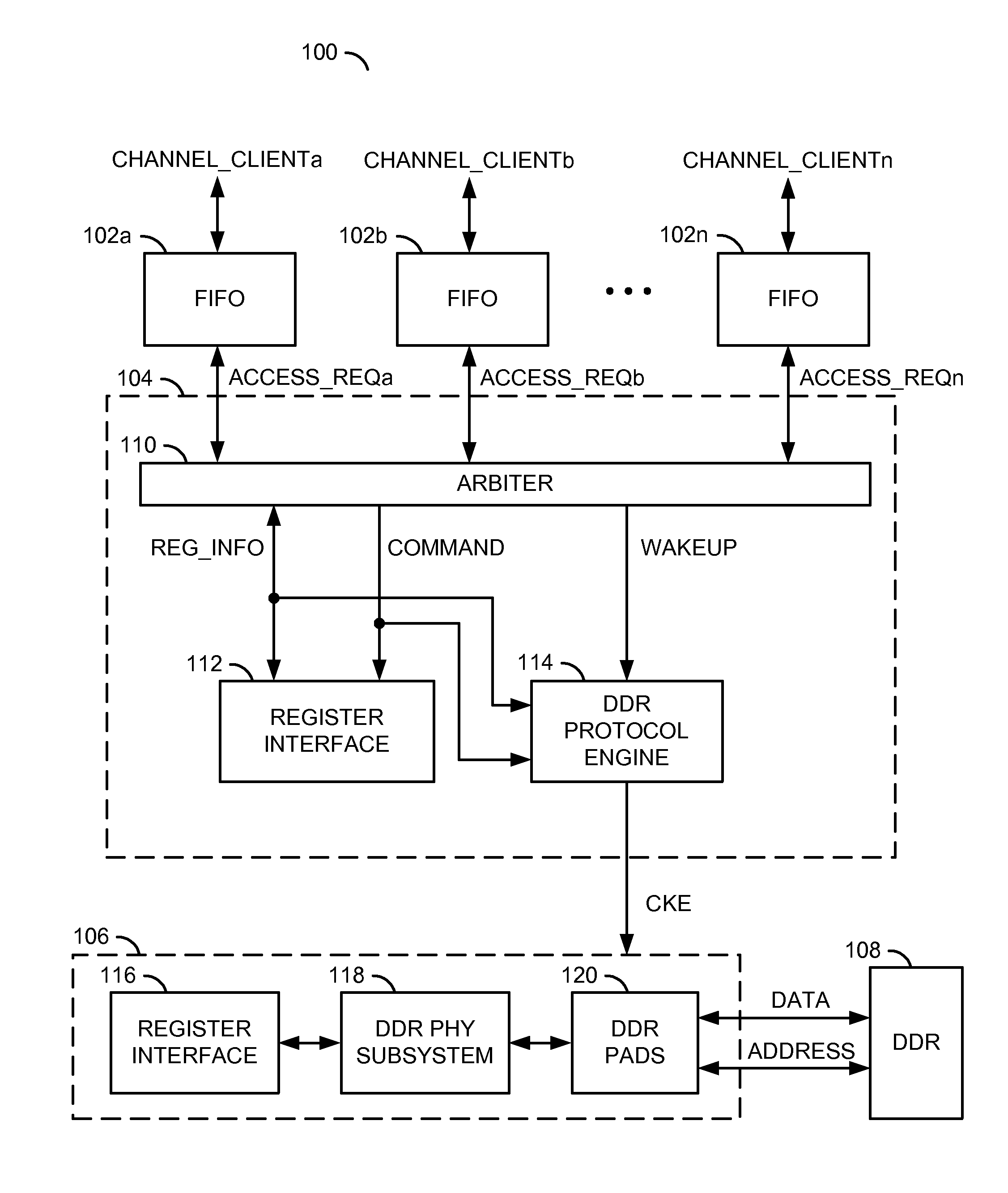
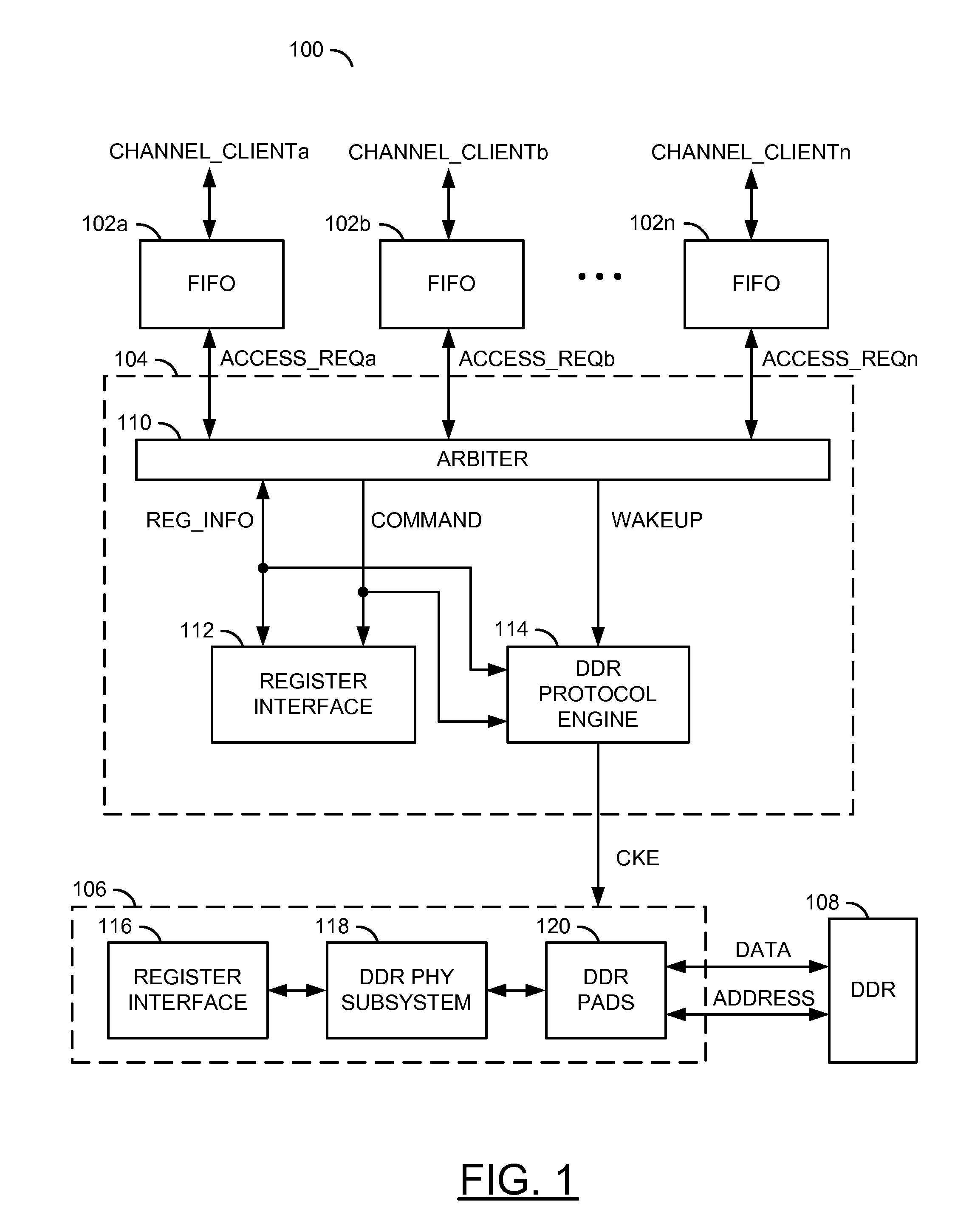
[0018]Referring to FIG. 1, a block diagram of a system 100 is shown in accordance with a preferred embodiment of the present invention. The system 100 generally comprises a plurality of blocks (or circuits) 102a-102n, a block (or circuit) 104, a block (or circuit) 106 and a block (or circuit) 108. The circuits 102a-102n may be implemented as a buffer circuits. For example, the circuits 102a-102n may be implemented as First-In First-Out (FIFO) memory circuits. The circuit 104 may be implemented as a memory controller circuit. The circuit 106 may be implemented as a memory PHY interface circuit. In one example, the circuit 106 may be implemented as a DDR PHY interface circuit. The circuit 108 may be implemented as a memory circuit.

[0019]The circuit 104 generally comprises a block (or circuit) 110, a block (or circuit) 112 and a block (or circuit) 114. The circuit 110 may be implemented as an arbiter circuit. The circuit 112 may be implemented as a register interface circuit. The circu...


PUM


Abstract

An apparatus comprising a plurality of buffers and a memory controller. The plurality of buffers may each be configured to generate an access request signal in response to a respective one of a plurality of channel requests received from a respective one of a plurality of clients. The memory controller circuit may be configured to generate a clock enable signal in response to the plurality of access request signals. The clock enable signal may be configured to initiate entering and exiting a power savings mode of a memory circuit.

Description

[0001]This application claims the benefit of U.S. Provisional Application No. 61 / 347,854, filed May 25, 2010 and is hereby incorporated by reference in its entirety.[0002]The application may also relate to co-pending application Ser. No. 12 / 857,716, filed Aug. 17, 2010, Ser. No. 12 / 899,681, filed Oct. 7, 2010 and Ser. No. 12 / 878,194, filed Sep. 9, 2010, which are each hereby incorporated by reference in their entirety.FIELD OF THE INVENTION[0003]The present invention relates to memories generally and, more particularly, to a method and / or apparatus for implementing power savings and / or dynamic power management for a memory through arbiter and protocol engine collaboration.BACKGROUND OF THE INVENTION[0004]Conventional memory controllers generally limit power management capabilities to firmware controlled implementations. Such approaches only allow deep, long-term, power reduction modes to be used given the relative slowness of the processor compared to the fast nature of the memory c...

Claims


Application Information

Patent Timeline
Patent Type & Authority Patents(United States)
IPC IPC(8): G11C7/00
CPCG06F1/3203G06F1/3275Y02B60/1228Y02B60/1225Y02D10/00
Inventor ARNTZEN, ESKILD T.ELLIS, JACKSON L.
Owner AVAGO TECH INT SALES PTE LTD
Why Eureka
Try Eureka