Method and system for controlling brake equipment which can be activated when a motor vehicle is stationary

a technology of brake equipment and stationary motor vehicles, which is applied in the direction of brake action initiation, braking systems, transportation and packaging, etc., can solve the problems of prefixing the braking force generated by the holding brake, parked motor vehicles rolling away, and motor vehicles in a state of standstill

Inactive Publication Date: 2008-07-22
LUCAS AUTOMOTIVE GMBH
View PDF20 Cites 18 Cited by
  • Summary
  • Abstract
  • Description
  • Claims
  • Application Information

AI Technical Summary

Benefits of technology

[0006]An object of the present invention is to provide a method and a system which make it possible to control a braking equipment adapted to be activated at standstill of a motor vehicle in such a manner that the braking forces necessary for the standstill are built up and maintained automatically. Moreover, the braking forces made available in the state of standstill have to be suitable to safeguard that a motor vehicle cannot roll away in different states of standstill.

Problems solved by technology

This may result in a parked motor vehicle rolling away for lack of it having been secured by the holding brake.
Especially in cases in which the motor vehicle is situated at an ascending or descending slope it is not guaranteed that the braking force of the holding brake generated in this manner is sufficient to keep the motor vehicle in a state of standstill.
It is a drawback in this connection that the braking force generated by the holding brake is prefixed.
It can therefore not be suitable to hold the motor vehicle at a standstill at a steep slope, for example.
A further drawback is that the holding brake is activated even if the accelerator pedal is not actuated, while the motor vehicle is in an driving mode.
This may result in undesired or uncontrollable driving states especially during high vehicle speed, e.g. when a vehicle driver does no longer actuate the accelerator pedal in order to operate the coupling pedal.
Here it is of disadvantage that no braking forces are made available at standstill without the brake pedal being actuated when reaching the state of standstill.
Moreover, it is not possible with this system to generate braking forces required for a standstill when the ignition of the motor vehicle is switched off:

Method used


Image

  • Method and system for controlling brake equipment which can be activated when a motor vehicle is stationary
  • Method and system for controlling brake equipment which can be activated when a motor vehicle is stationary
  • Method and system for controlling brake equipment which can be activated when a motor vehicle is stationary

Examples


Embodiment Construction

[0025]In accordance with the provisions of the patent statutes, the principle and mode of operation of this invention have been explained and illustrated in its preferred embodiment. However, it must be understood that this invention may be practiced otherwise than as specifically explained and illustrated without departing from its spirit or scope.

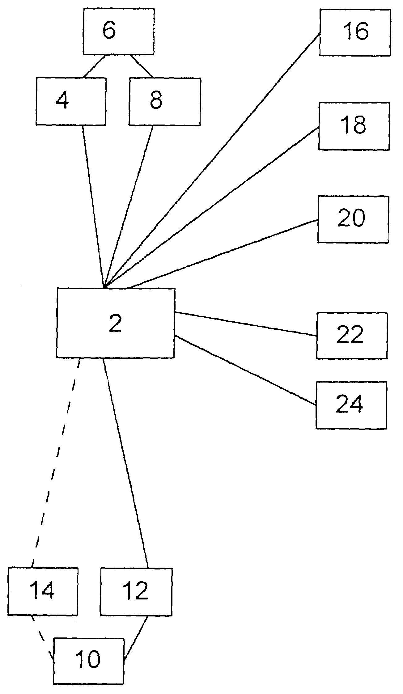
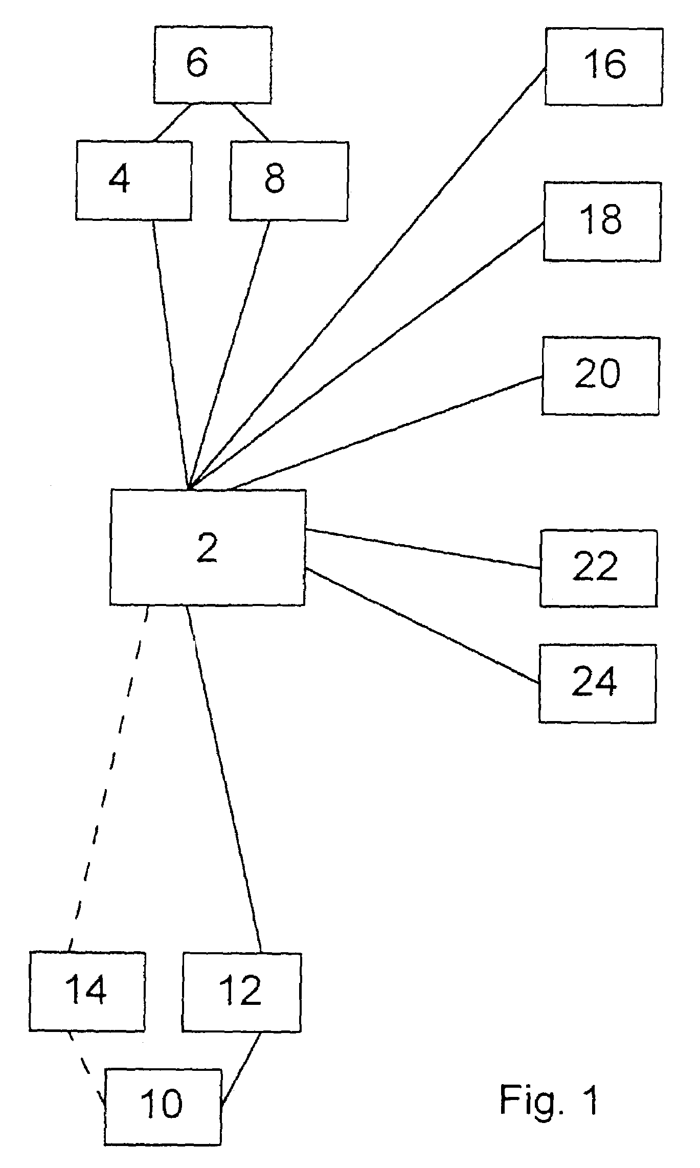
[0026]The system 1 for controlling a braking equipment adapted to be activated in the state of standstill of a motor vehicle illustrated in FIG. 1 may be a separately constructed equipment of the motor vehicle, utilize, at least partially, already present components of further systems of the motor vehicle, or be comprised by a system making further control functions for the motor vehicle available.

[0027]The system 1 comprises a control unit 2 controlling a holding brake mechanism 6 of a motor vehicle (not shown) via an interface 4. The control unit 2 detects parameters characterizing the current operating state of the holding brake mechan...


PUM


Abstract

The present invention provides a method and a system for controlling a braking equipment of a motor vehicle in order to activate the braking equipment at a standstill of the motor vehicle such that braking forces are built up which are necessary to keep the motor vehicle in a state of standstill. To this end it is established on the basis of vehicle movements whether the vehicle is at a standstill. If vehicle movements are detected that cannot occur during driving modes of the motor vehicle, the motor vehicle is in a state of standstill. Subsequently, the braking equipment, and in particular a holding brake mechanism included in the braking equipment, are activated. In order to provide braking forces keeping the motor vehicle at a standstill also when it is on a slope, the braking equipment, and in particular the holding brake mechanism, are controlled in response of the vehicle inclination present in the state of standstill.

Description

CROSS REFERENCE TO RELATED APPLICATIONS[0001]This application is a continuation of International Application No. PCT / EP01 / 14943 filed Dec. 18, 2001, the disclosures of which are incorporated herein by reference, and which claimed priority to German Patent Application No. 100 62 063.4 filed Dec. 18, 2000, the disclosures of which are incorporated herein by reference.[0002]The present invention relates to a method and a system for controlling the braking equipment of a motor vehicle which, when the motor vehicle is at a standstill, is adapted to be activated in an automatically controlled manner to build up braking forces in order to keep the motor vehicle in a state of standstill. In particular, the present invention relates to a method and a system in which, based on movements typical of a driving operation of the motor vehicle such as pitching movements, it is detected whether the motor vehicle is at a standstill or not in order to activate the braking equipment at a state of stand...

Claims


Application Information

Patent Timeline
Patent Type & Authority Patents(United States)
IPC IPC(8): B60K28/10B60T7/12B60T11/10
CPCB60T7/122B60T11/103B60T2201/06B60T7/12
Inventor KINDER, RALFKLAPPER, GERHARDSHOKOUFANDEH, REZAENDRES, FRANZ-JOSEFLEITER, RALFMAACK, LORENZSONS, ANDREAS
Owner LUCAS AUTOMOTIVE GMBH
Why Eureka
Try Eureka