System for driving a wire loop cutting element

a cutting element and wire loop technology, applied in the direction of band saws, underwater equipment, saw chains, etc., can solve the problems of large clearance and cumbersome movement of such multiple cutting means

Active Publication Date: 2008-08-05
OCEANEERING INTERNATIONAL
View PDF21 Cites 29 Cited by
  • Summary
  • Abstract
  • Description
  • Claims
  • Application Information

AI Technical Summary

Problems solved by technology

The movement of such multiple component cutting means is often cumbersome and requires significant clearance on multiple sides of the object to be cut.

Method used


Image

  • System for driving a wire loop cutting element
  • System for driving a wire loop cutting element
  • System for driving a wire loop cutting element

Examples


Embodiment Construction

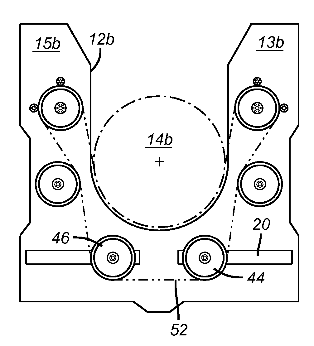
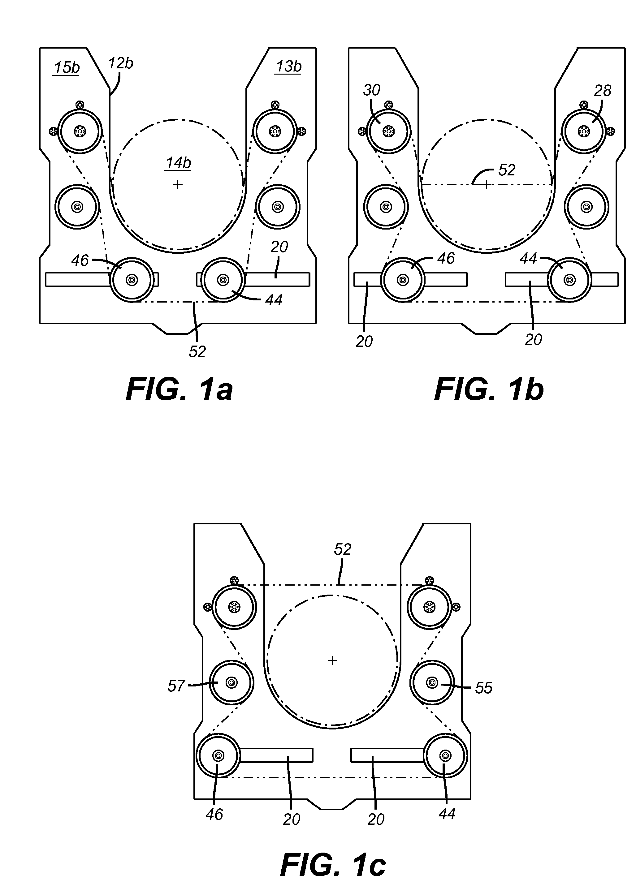
[0015]As shown in FIGS. 1a-1c and 3, a first preferred embodiment of the invention comprises a frame 10 comprising a lower plate 12a comprising right arm 13a and left arm 15a defining a lower central gripping region 14a. The frame further comprises a bracket 16 connected to the lower plate, and an upper plate 12b connected to the bracket. The upper plate comprises two pulley slots 20, a right arm 13b comprising a first drive wheel axle opening 22, and a left arm 15b opposite the right arm, comprising a second drive wheel axle opening 24. The right and left arms define an upper central gripping region 14b in substantial longitudinal alignment with the lower central gripping region, as shown in FIG. 1a.

[0016]In another preferred embodiment, the frame further comprises a buoyant member 26, as shown in FIG. 3. In a preferred embodiment, the buoyant member is foam.

[0017]As shown in FIGS. 1a-1c, 3, and 4, a first preferred embodiment of the invention further comprises a first drive wheel...


PUM

PropertyMeasurementUnit
separation distanceaaaaaaaaaa
diameteraaaaaaaaaa
movementaaaaaaaaaa

Abstract

This invention is directed toward a system for driving a wire loop cutting element. More particularly, the disclosed invention employs a frame and pulleys to drive a wire loop cutting element.

Description

FIELD OF THE INVENTION[0001]This invention is directed toward a system for driving a wire loop cutting element. More particularly, the disclosed invention employs a frame and pulleys to drive a wire loop cutting element.BACKGROUND OF THE INVENTION[0002]Prior art systems exist for cutting subsea structures. One such system is disclosed in U.S. Pat. No. 5,361,748 to Matteucci. Prior art cutting systems have employed multiple component cutting means comprising pulleys, a cutting blade and related structure, which must move so as to traverse the diameter of the object to be cut. The movement of such multiple component cutting means is often cumbersome and requires significant clearance on multiple sides of the object to be cut.[0003]The present invention overcomes such drawbacks by providing a cutting system wherein traversal of the diameter of the object to be cut by a multiple component cutting means is not required.DESCRIPTION OF THE DRAWINGS[0004]FIG. 1a is a top view of an embodime...

Claims


Application Information

Patent Timeline
Patent Type & Authority Patents(United States)
IPC IPC(8): B26D1/44
CPCB23D57/0061B26D1/547B23D57/0084Y10T83/7239Y10T83/9292B23D53/001B23D57/0053B63C11/52
Inventor LAWLER, KINTONDAVIS, JOHNPIECYK, MICHAEL
Owner OCEANEERING INTERNATIONAL
Why Eureka
Try Eureka