Optical branching module and optical cable boot

a branching module and optical cable technology, applied in the field of optical branching, can solve the problem of increasing the loss of optical transmission

Active Publication Date: 2008-08-05
THE FUJIKURA CABLE WORKS LTD
View PDF6 Cites 16 Cited by
  • Summary
  • Abstract
  • Description
  • Claims
  • Application Information

AI Technical Summary

Benefits of technology

[0014]In accordance with exemplary embodiments of the present invention, an optical branching module in which the fixing force for the cables is strong can be provided.
[0016]In accordance with an exemplary embodiment of the present invention, an optical connector boot can be provided, which, even in the case of being applied with the pulling force in the direction of 90 degrees with respect to a cabling direction of the optical fibers or the optical cables, is bent at a predetermined spot, and is gently curved as a whole, thus making it possible to moderate the bending of the optical fibers, and to reduce the optical transmission loss.

Problems solved by technology

Accordingly, when a pulling load is applied to a direction (downward in FIG. 3) of 90 degrees with respect to a direction where the optical connector is attached / detached onto / from the optical fibers, the optical fibers are not curved into a shape shown by the dotted lines of FIG. 3B, but are positionally shifted therefrom in a shearing direction at the coupling portions 335 of the slits 335, the optical fibers are bent at an acute angle, and the side thrust is increased, resulting in a problem that the optical transmission loss is increased.

Method used


Image

  • Optical branching module and optical cable boot
  • Optical branching module and optical cable boot
  • Optical branching module and optical cable boot

Examples


first exemplary embodiment

[0045]A description will be made below in detail of an optical connector boot according to an exemplary embodiment of the present invention based on the drawings. FIG. 4 to FIG. 11 show an exemplary embodiment of the present invention. FIG. 4 is a schematic configuration view showing a state where the optical connector boot is used. FIG. 5 is a perspective view of the optical connector boot. FIG. 6 is a front view showing a cross-section of a part of the optical connector boot. FIG. 7 is a bottom view showing the cross section of the part of the optical connector boot. FIG. 8 is a right side view of the optical connector boot. FIG. 9 is a left side view of the optical connector boot. FIGS. 10A and 10B are conceptual views showing a function of the optical connector boot: FIG. 10A is a view before a load is applied to the optical connector boot; and FIG. 10B is a view where the load is applied thereto. FIG. 11 is a cross-sectional view taken along a line A-A of FIG. 4, showing positi...

second exemplary embodiment

[0080]A description will be made of an exemplary embodiment of the present invention based on the drawings.

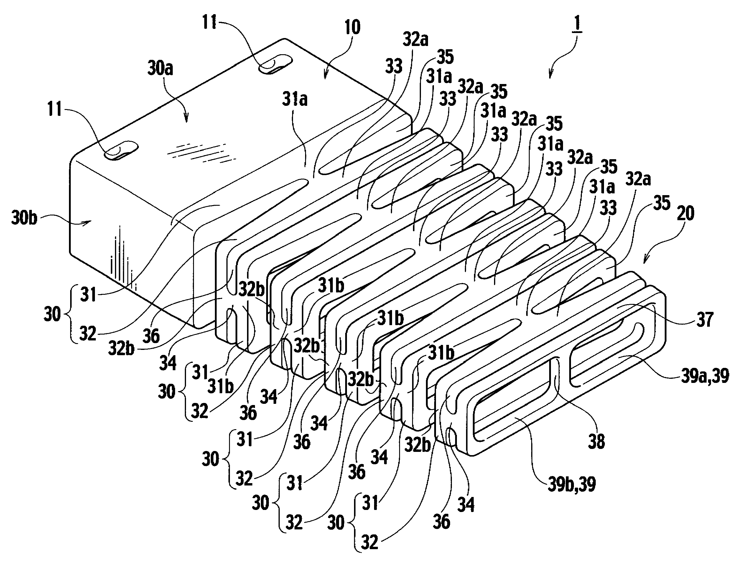
[0081]FIG. 14 to FIG. 26 show an exemplary embodiment of the present invention. FIG. 14 is a plan view of an optical branching module from which a cover is detached. FIG. 15A is an enlarged cross-sectional view taken along a line A-A of FIG. 14. FIG. 15B is an enlarged cross-sectional view taken along a line B-B of FIG. 14. FIG. 16 is a exploded perspective view of the optical branching module. FIG. 17 is a front view of a one end of an optical fiber cable (hereinafter, referred to as an optical cable or a cable). FIG. 18 is a perspective view of an output-cable fixing member and a cable support plate. FIG. 19 is a plan view of the output-cable fixing member onto which the cable support plate is attached. FIG. 20 is a plan view of the output-cable fixing member in which cables on an output side are inserted into cable insertion holes. FIG. 21 is a plan view of the output-cable ...


PUM


Abstract

An optical branching module includes a case from which cables are drawn out and an output-cable fixing member attached onto the case by insertion. Optical cables are inserted into cable insertion holes of the optical cable fixing member, and the optical cables are fixed to the optical cable fixing member by an adhesive applied from an opening portion. The optical branching module includes a cable boot configured not to be bent in a radius of curvature smaller than the allowed radius of curvature of the optical cables.

Description

This application claims priority from Japanese Patent Applications No. 2006-333743, filed on Dec. 11, 2006, and No. 2007-192497, filed on Jul. 24, 2007, the entire contents of which are incorporated by reference herein.BACKGROUND OF THE INVENTION[0001]1. Field of the Invention[0002]Apparatuses consistent with the present invention relate to an optical branching module that performs optical signal processing such as optical branching for an optical signal inputted by an optical cable on an input side, and outputs optical signals subjected to optical signal processing by optical cables on an output side, and particularly, to an optical splitter module that contains an optical splitter and to an optical connector boot.[0003]2. Description of the Related ArtOptical Branching Module[0004]In general, in an optical branching module, for example, cables on an input side and an output side are drawn out of a case. The cables drawn out of the optical branching module are fixed thereto so as n...

Claims


Application Information

Patent Timeline
Patent Type & Authority Patents(United States)
IPC IPC(8): G02B6/36G02B6/00G02B6/38
CPCG02B6/4471G02B6/3889G02B6/4441G02B6/4478G02B6/38875
Inventor MOMOTSU, TOSHIHIROKATAYOSE, KOICHI
Owner THE FUJIKURA CABLE WORKS LTD
Why Eureka
Try Eureka