Ribbed pipe clamp with sealing sleeve

a technology of sealing sleeves and pipe clamps, which is applied in the direction of hose connections, snap fasteners, machines/engines, etc., can solve the problems that the band clamps disclosed in the potts patent do not provide a sufficiently strong and gas-tight connection for certain automotive exhaust applications

Active Publication Date: 2008-08-12
BREEZE TORCA PRODS
View PDF10 Cites 28 Cited by
  • Summary
  • Abstract
  • Description
  • Claims
  • Application Information

AI Technical Summary

Problems solved by technology

Although the band clamps of the Potts patent can be used for exhaust component canisters and smaller diameter pipes as well, the inventors have found that the design of the band clamps disclosed in the Potts patent do not provide a sufficiently strong and gas-tight connection for certain automotive exhaust applications.

Method used


Image

  • Ribbed pipe clamp with sealing sleeve
  • Ribbed pipe clamp with sealing sleeve
  • Ribbed pipe clamp with sealing sleeve

Examples


Embodiment Construction

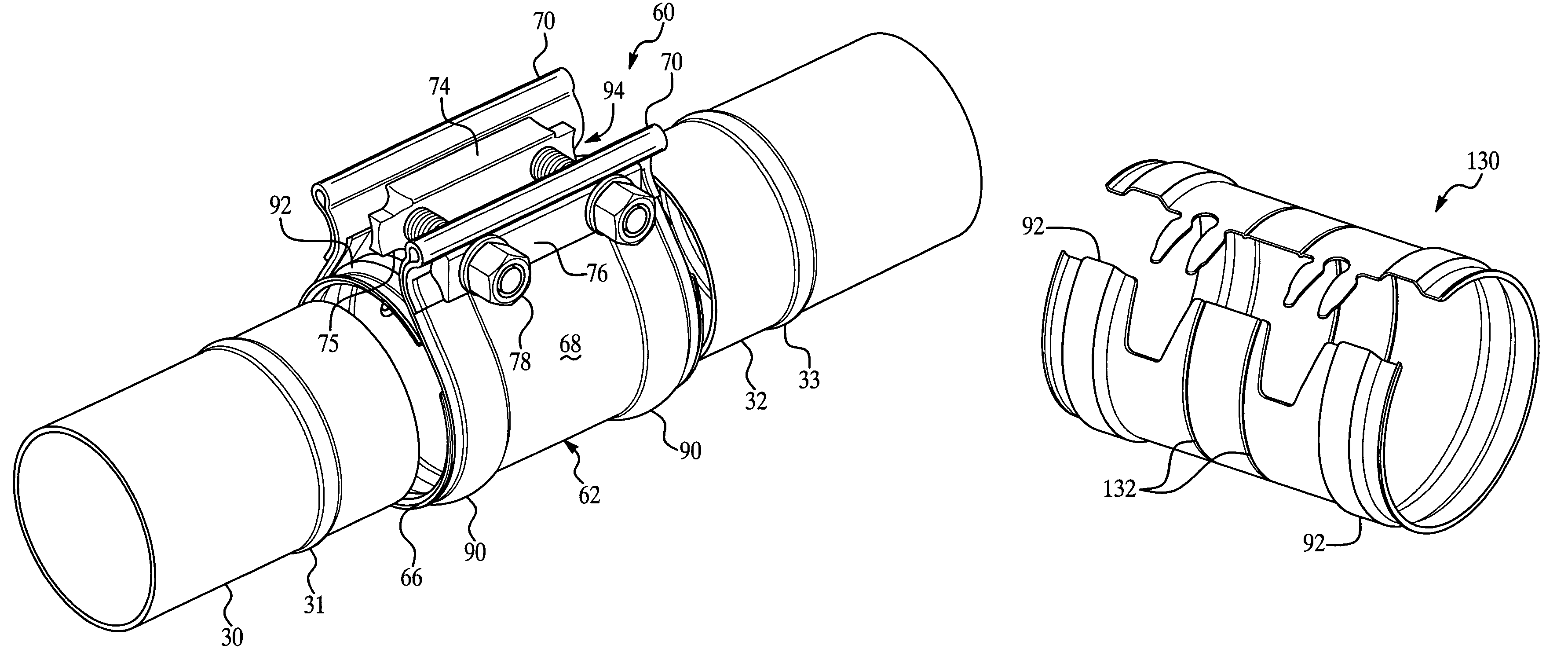
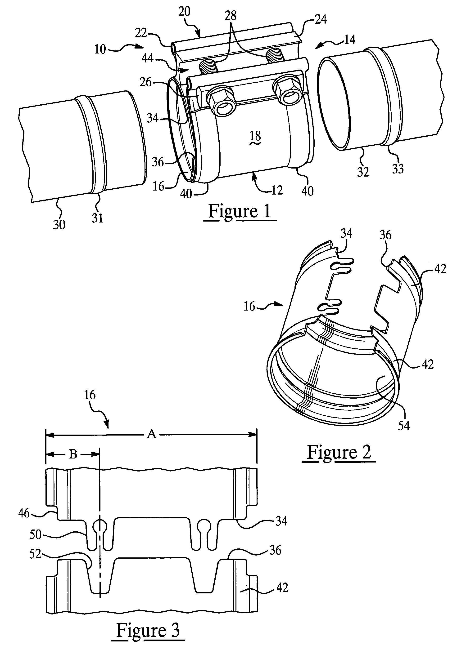
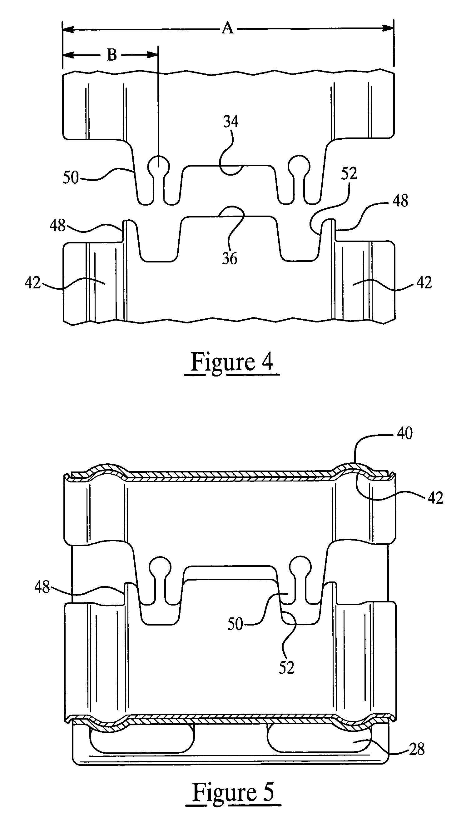
[0019]In the drawings there are shown various embodiments of the invention each in the form of a pipe coupler especially adapted for use in automotive engine exhaust systems. It will be appreciated as the description proceeds that the invention is useful in many different applications and in a wide variety of embodiments. For example, the invention can be used not only for pipe couplers that permit connecting ribbed pipes in an end-to-end configuration, but also for band clamps that are typically clamped over a pair of telescopically-connected pipes. As used herein, the term “pipe clamp” is used to refer to both pipe couplers and band clamps. Furthermore, the terms axially, angularly, and radially refer to directions relative to the circular (roundish) shape of the illustrated pipes and pipe coupler, so that the axial direction extends along the axis of this roundish shape, radial directions extend radially away from this axis, and angularly refers to locations at points around the ...


PUM


Abstract

A pipe coupler for use in connecting a pair of automotive exhaust pipe ends each having a circumferential rib. The pipe coupler includes a ribbed band and internal split sealing sleeve along with a tightening mechanism for clamping the band and sleeve over the pipe ends. The sealing sleeve fits within the band and both the sleeve and band have a pair of ribs positioned to fit over the ribs on the pipe ends. The sleeve extends circumferentially from a first end to a second end, and includes a tongue-and-groove sealing configuration located axially inwardly of the ribs at the first and second ends. Each tongue has a particular construction that accommodates larger clamp opening dimensions required to fit the coupler over the pipe ribs during assembly. The sleeve can include inwardly protruding sealing beads that help prevent leakage of exhaust gases from the pipe junction.

Description

CROSS-REFERENCE TO RELATED APPLICATION[0001]This application claims the priority of U.S. Provisional Application No. 60 / 574,339, filed May 25, 2004, the entire contents of which are hereby incorporated by reference.FIELD OF THE INVENTION[0002]This invention relates generally to pipe clamps and, more specifically, to both band clamps and pipe couplers used for connecting pipes or other tubular members together either telescopically or in an end-to-end configuration.BACKGROUND OF THE INVENTION[0003]A typical vehicle exhaust system includes an assembly of tubes, or pipes, that provide transport of engine exhaust gases. Each individual pipe section is connected to another pipe section to form a complete exhaust system assembly. Such connections are usually either telescopic or as an end-to-end abutting connection. To be effective, the connection formed between these pipes should provide a suitable fluid-tight seal against exhaust gas leakage. The connection should also have a high degre...

Claims


Application Information

Patent Timeline
Patent Type & Authority Patents(United States)
IPC IPC(8): F16L21/02F16L17/00F16L33/22F01N13/08F16L21/00F16L21/06F16L23/08
CPCF16L21/065F16L23/08F16L21/005F01N13/1855F01N13/1805F01N13/1827F01N13/1872Y10T24/1441Y10T24/1457F16L21/00F16L21/06
Inventor IGNACZAK, BRIAN T.AMEDURE, MICHAEL E.POLASKI, ALANLEE, KEVIN
Owner BREEZE TORCA PRODS
Why Eureka
Try Eureka