Diversionary device

a technology of diversion device and diversion chamber, which is applied in the direction of firecrackers, fire grenades, repellent gas/chemical self-defence devices, etc., can solve the problem of disorienting flash caused by powder ignition

Inactive Publication Date: 2008-08-19
LAW ENFORCEMENT TECH
View PDF20 Cites 20 Cited by
  • Summary
  • Abstract
  • Description
  • Claims
  • Application Information

AI Technical Summary

Problems solved by technology

The ignition of the powder creates a disorientating flash.

Method used


Image

  • Diversionary device
  • Diversionary device
  • Diversionary device

Examples


Embodiment Construction

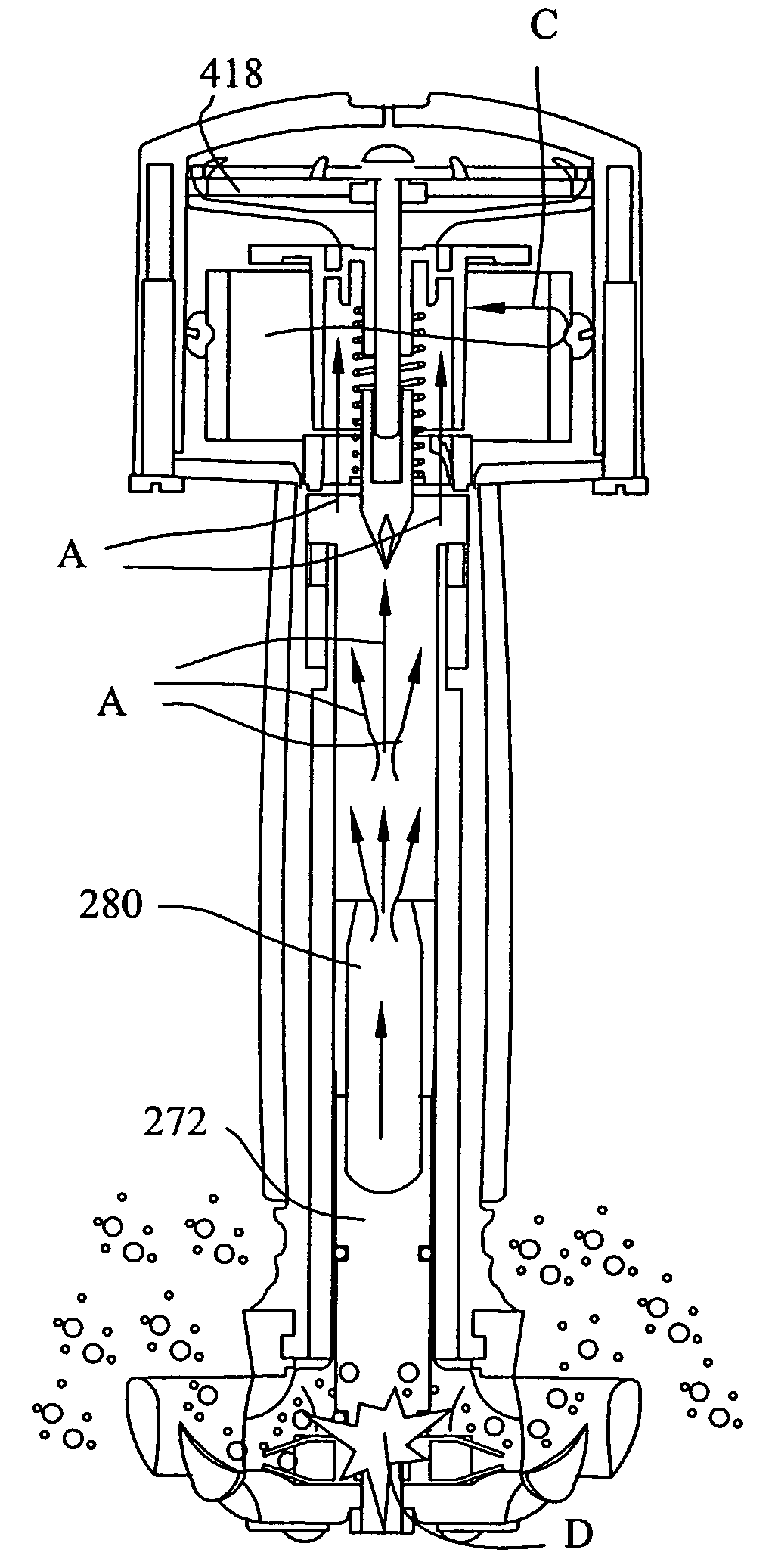
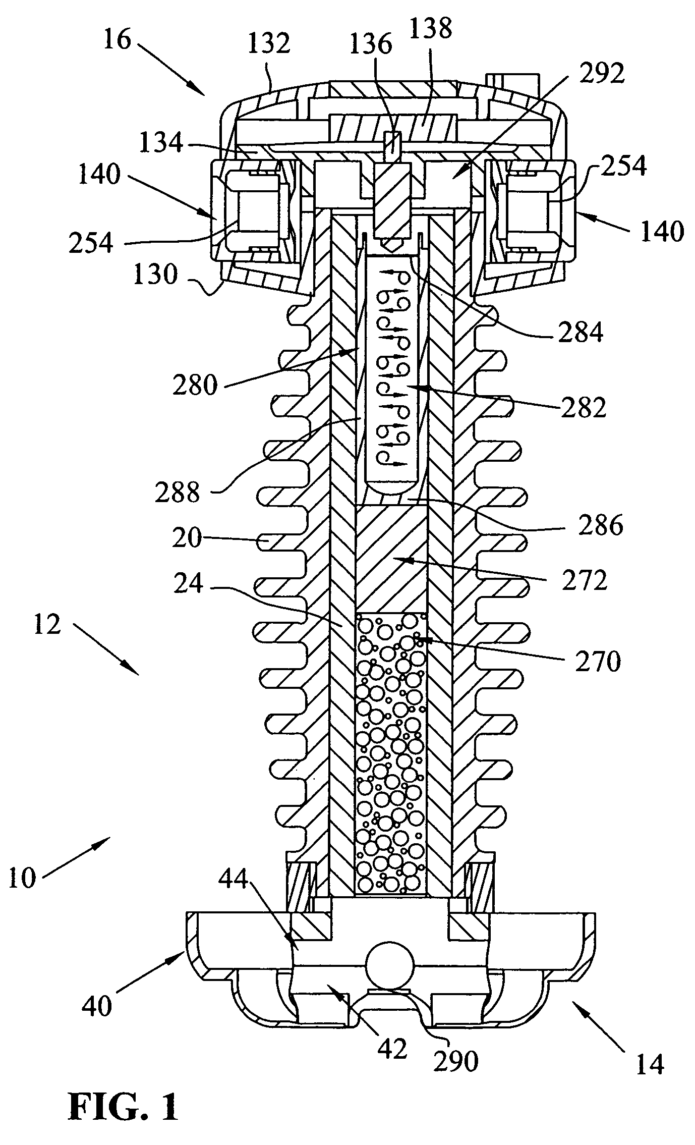
[0074]Referring first to FIG. 1, numeral 10 generally indicates a device for creating a diversion. In the relevant art, devices in the same family as device 10 are commonly referred to as “flash” grenades or “stun” grenades. Device 10 includes a housing, generally indicated by numeral 12, a dispersal mechanism, generally indicated by numeral 14, and a firing mechanism, generally indicated by numeral 16.

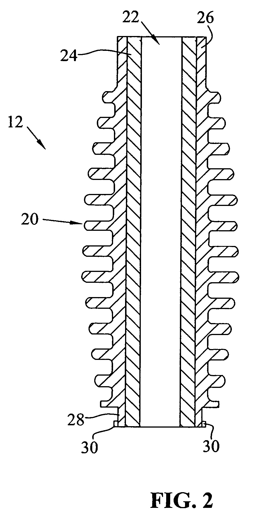
[0075]FIG. 2 shows a section view of housing 12. Housing 12 includes a handle portion 20 having a central bore 22 extending the length of handle portion 20. In the embodiment depicted, handle portion 20 is configured to provide a comfortable grip to a user. Handle portion 20 may be manufactured from any durable material, such as metal or plastic.

[0076]Housing 12 further includes a sleeve 24 sized and configured to be retained within bore 22 intermediate a first end 26 and a second end 28 of handle portion 20. In the present embodiment, sleeve 24 is manufactured of metal. It should be ...


PUM


Abstract

A diversion device capable of generating a disorientating flash and a disorientating sound without an explosion has a housing with a cavity containing an inert gas, a piston and a powder. The powder creates the flash via ignition after exiting the device. The device also includes a mechanism configured to ensure the powder encompasses the device upon exit and does is not dispersed in a substantially horizontal plane. In addition, the device may include devices capable of creating a disorientating sound as the inert gas escapes the device.

Description

BACKGROUND OF THE INVENTION[0001]This invention relates to diversionary devices used in a variety of military and law enforcement situations. Specifically, the device provides a mechanism to disorientate an adversary without inflicting permanent damage or harm. The device accomplishes this by producing a disorientating flash of light and a confusingly loud noise. Devices of this sort are often referred to as “stun grenades” or “flash grenades.”[0002]Several patents disclose hand held diversionary devices. For example, U.S. Pat. No. 4,947,753 granted to Nixon discloses a “stun grenade” configured to produce non-lethal explosions. The disclosed stun grenade includes an elongated body having a hollow interior with an explosive substance located therein. The stun grenade further includes an igniter fuse attached to the grenade body for creating an ignition spark. The ignition spark causes the explosive substance to explode in a non-lethal manner.[0003]U.S. Pat. No. 5,654,523 granted to ...

Claims


Application Information

Patent Timeline
Patent Type & Authority Patents(United States)
IPC IPC(8): F42B12/46F42B27/00F42B4/18
CPCF41H9/10F42B4/04F42B4/16F42B27/00F42B12/36F42B12/42F42B12/50F42B8/26
Inventor WALSH, ROBERT
Owner LAW ENFORCEMENT TECH
Why Eureka
Try Eureka