Locking device of sliding drawer

a locking device and drawer technology, applied in drawers, furniture parts, domestic applications, etc., can solve the problems of drawers falling out of the cabinet body easily without warning, damage to the drawer or the sliding path, and the design of sliding drawers

Inactive Publication Date: 2008-08-19
NAN JUEN INT CO LTD
View PDF2 Cites 18 Cited by
  • Summary
  • Abstract
  • Description
  • Claims
  • Application Information

AI Technical Summary

Benefits of technology

[0007]It is an object of the present invention to provide an improved design of a sliding drawer that can overcome the conventional design defaults.
[0008]It is another object of the present invention to provide an improved locking device structure that can be easily slid in / out of a cabinet body, and can secure the location of the sliding drawer within the cabinet body without causing any harm or danger.

Problems solved by technology

Those conventional sliding drawer's designs constitute some problems.
When the drawer is slid in and out from the cabinet body, the slight vibration resulted from the external force or the collision would cause the drawer falling out from the cabinet body easily without warning.
The unpleasant mess caused by falling out of objects from the drawer and the damage to the drawer or the sliding paths is a big problem.
Furthermore, this kind of design of sliding drawer can cause seriously body harm to the user when the sliding drawer falls out.
This design still cannot secure the sliding drawer in the cabinet body during moving or earthquake activity, when the incline angle is increased, the sliding drawer can be slid out from the cabinet body easily resulting greater damage.
Once the locking key is lost, it creates inconvenience to the user.
Therefore, those conventional designs of the sliding drawers constitute some defaults and inconvenience to the users.

Method used


Image

  • Locking device of sliding drawer
  • Locking device of sliding drawer
  • Locking device of sliding drawer

Examples


Embodiment Construction

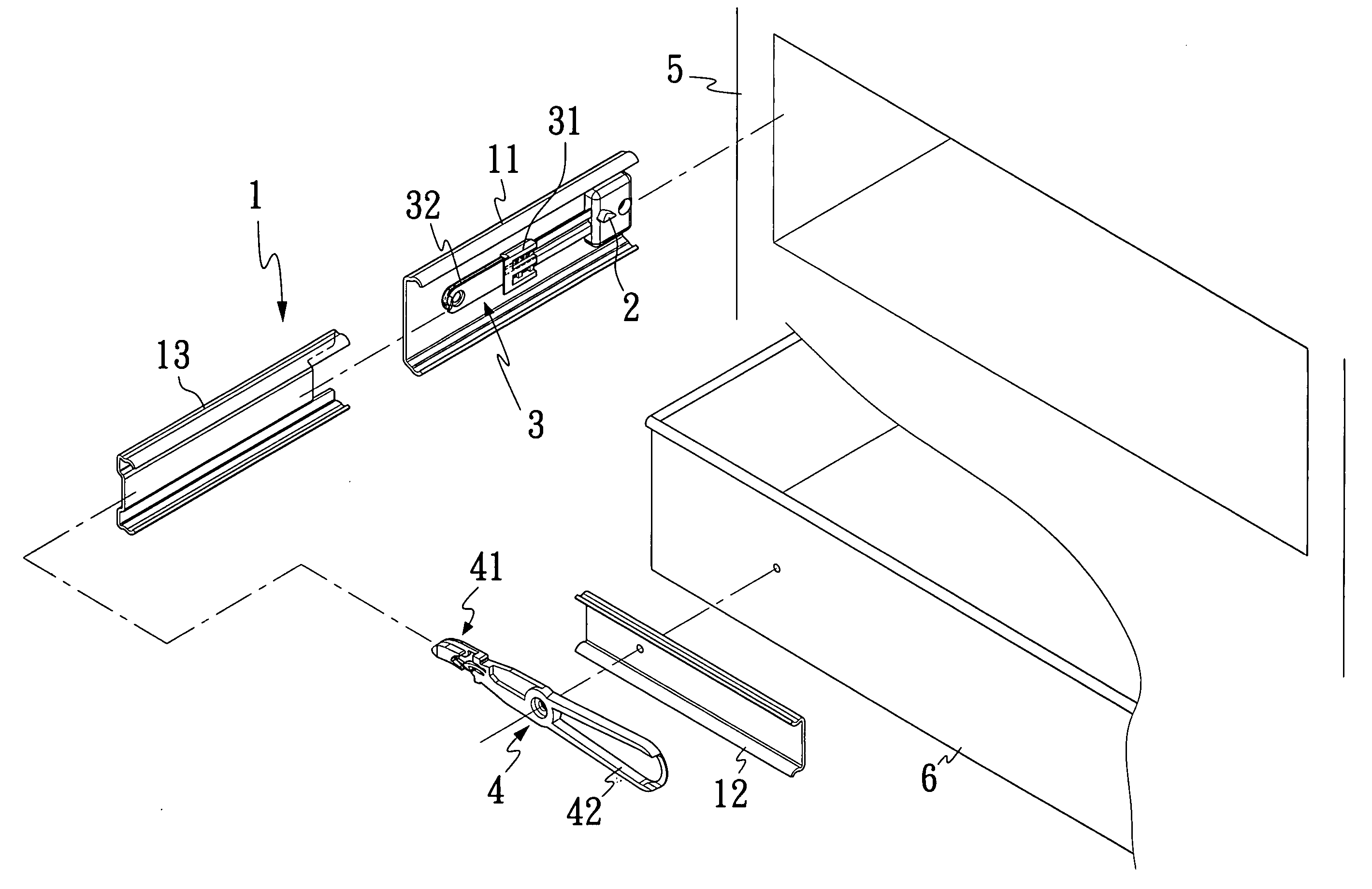
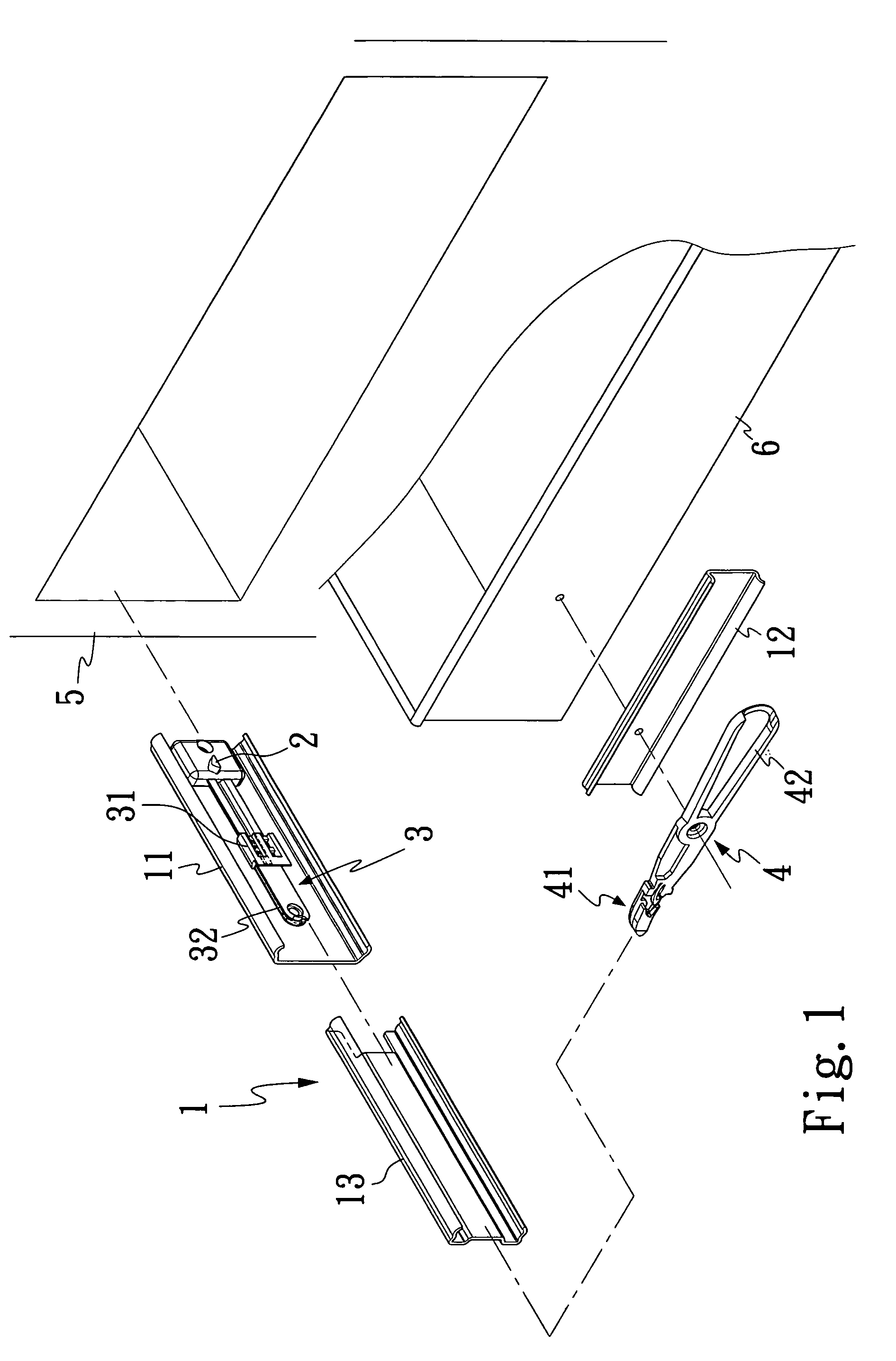
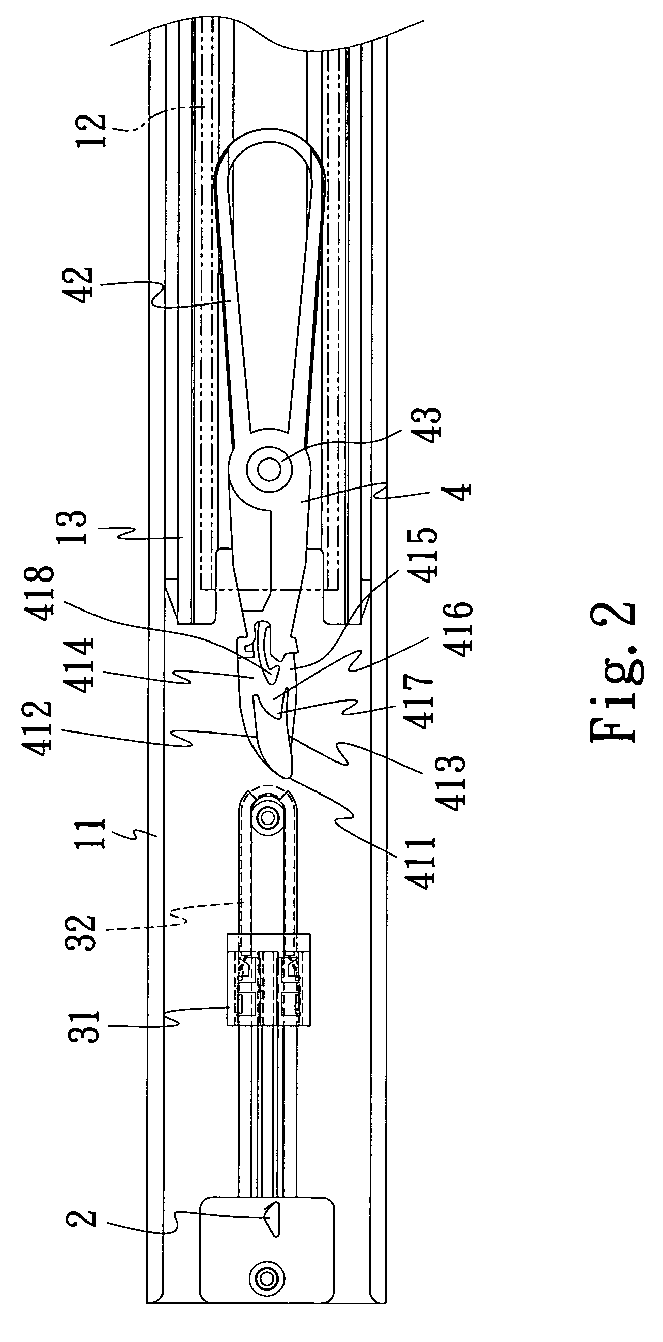
[0020]FIGS. 1 and 2 illustrate views of a locking device of sliding drawer in accordance with a preferred example of the present invention. The locking device of sliding drawer comprises a sliding trail 1, a protruding portion 2, a flexible device 3 and a locking device 4. The sliding trail 1 further comprises three sliding tracks, wherein a first sliding track 11 is installed in a cabinet body 5. A second sliding track 12 is provided as an external track outside a drawer 6, whereas a middle sliding track 13 is located in between the first sliding track 11 and the second sliding track 12. The protruding portion 2 is formed into a triangular prism shaped structure, and a flexible device area provided within the first sliding track 11. The flexible device 3 includes a sliding body 31 and a flexible unit 32, wherein the sliding body 31 and the flexible unit 32 are both installed in the first sliding track 11. The sliding body 31 is assembled in the first sliding track 11 and can be mov...


PUM


Abstract

An improved locking device of sliding drawer comprises a sliding rail and a locking device, when the sliding drawer is pushed back to a cabinet body, the locking device is initiated when a second sliding track moves along the sliding rail towards a direction of the cabinet body. When one of the circumferential parts of the locking device comes into contact with a protruding portion of a first sliding track, an attaching portion is rotated around the rotating shaft at a rotation center thereby biasing a flexible part of the locking device and generating a first restoring force, a flexible device of the first sliding track is triggered by the second sliding track to generate a second restoring force, when the protruding portion is inserted through the trench and seated within the arc-shaped structure, the first restoring force of the flexible device is released such that the drawer is now locked within the cabinet body.

Description

BACKGROUND OF THE INVENTION[0001]1. Field of Invention[0002]The present invention relates a locking device of sliding drawer particularly the present invention relates a locking device of a sliding drawer, capable of locking the drawer within a cabinet body automatically, when it is being pushed back to the cabinet body.[0003]2. Description of the Related Art[0004]Present-day, the main objective of the conventional designs of the sliding drawers in the market is to increase the convenient operation of the sliding drawer. Most of the conventional designs are used to install one end of two sliding paths onto the inner sides of a cabinet body. Another two sliding paths are provided at the external sides of the cabinet body so that the drawer can be pushed in and out. Ball shaped objects, such as bearings or rollers are designed within the sliding paths to increase the sliding movement of the drawer. Those conventional sliding drawer's designs constitute some problems. When the drawer i...

Claims


Application Information

Patent Timeline
Patent Type & Authority Patents(United States)
IPC IPC(8): A47B88/04
CPCA47B88/047A47B88/467
Inventor CHANG, GUEY-YUNHUANG, KUO-SHENG
Owner NAN JUEN INT CO LTD
Why Eureka
Try Eureka