
Rendering apparatus, rendering processing method and computer program product

a technology of rendering apparatus and computer program product, which is applied in the direction of fluid pressure computing, analog and hybrid computing, instruments, etc., can solve the problems of high cost, complicated clipping, and high processing requirements

Inactive Publication Date: 2008-08-19
KK TOSHIBA
View PDF7 Cites 14 Cited by
  • Summary
  • Abstract
  • Description
  • Claims
  • Application Information

AI Technical Summary

Problems solved by technology

The clipping is complicated, and much processings are required.
For this reason, dedicated hardware is frequently required; as a result, there is a possibility that the cost becomes high.

Method used


Image

  • Rendering apparatus, rendering processing method and computer program product
  • Rendering apparatus, rendering processing method and computer program product
  • Rendering apparatus, rendering processing method and computer program product

Examples


Embodiment Construction

[0056]Embodiments of the present invention will be described below with reference to the accompanying drawings. In the following description, the same reference numerals are used to designate elements having the identical function and configuration, and the overlapping explanation will be made if necessary only.

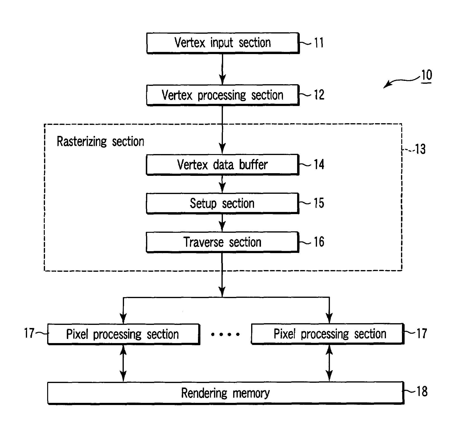
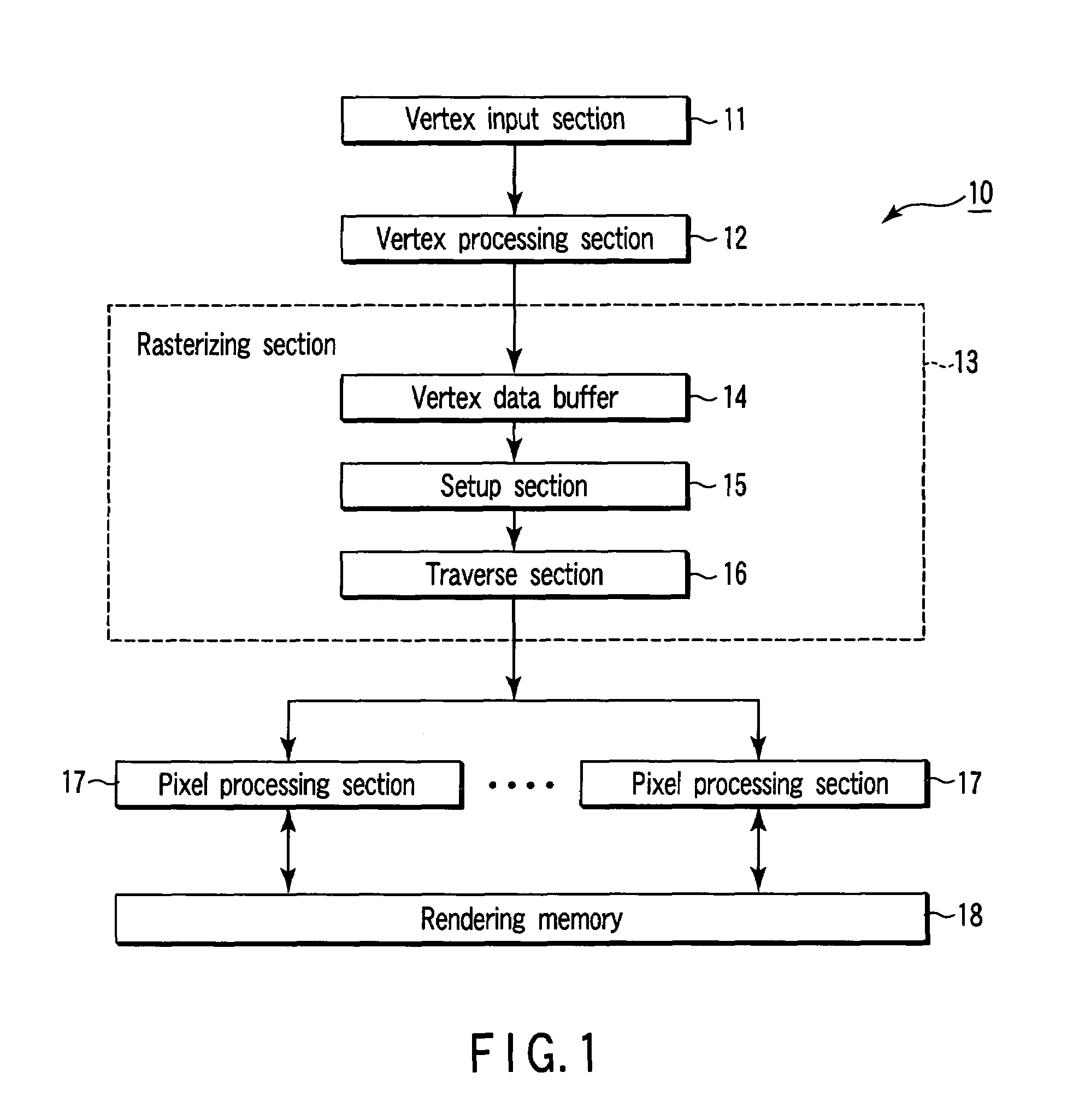
[0057]FIG. 1 is a block diagram showing the configuration of a real-time CG processor (engine) 10 according to an embodiment of the present invention. As shown in FIG. 1, the graphic processor 10 includes vertex input section 11, vertex processing section 12, rasterizing section 13, pixel processing section 17 and rendering memory 18.

[0058]The vertex input section 11 inputs vertex data of rendering primitive from a predetermined storage device.

[0059]The vertex processing section 12 makes an operation of predetermined coordinate transformation with respect to the vertex data inputted from the vertex input section 11.

[0060]The rasterizing section 13 carries out rasterizing to g...


PUM


Abstract

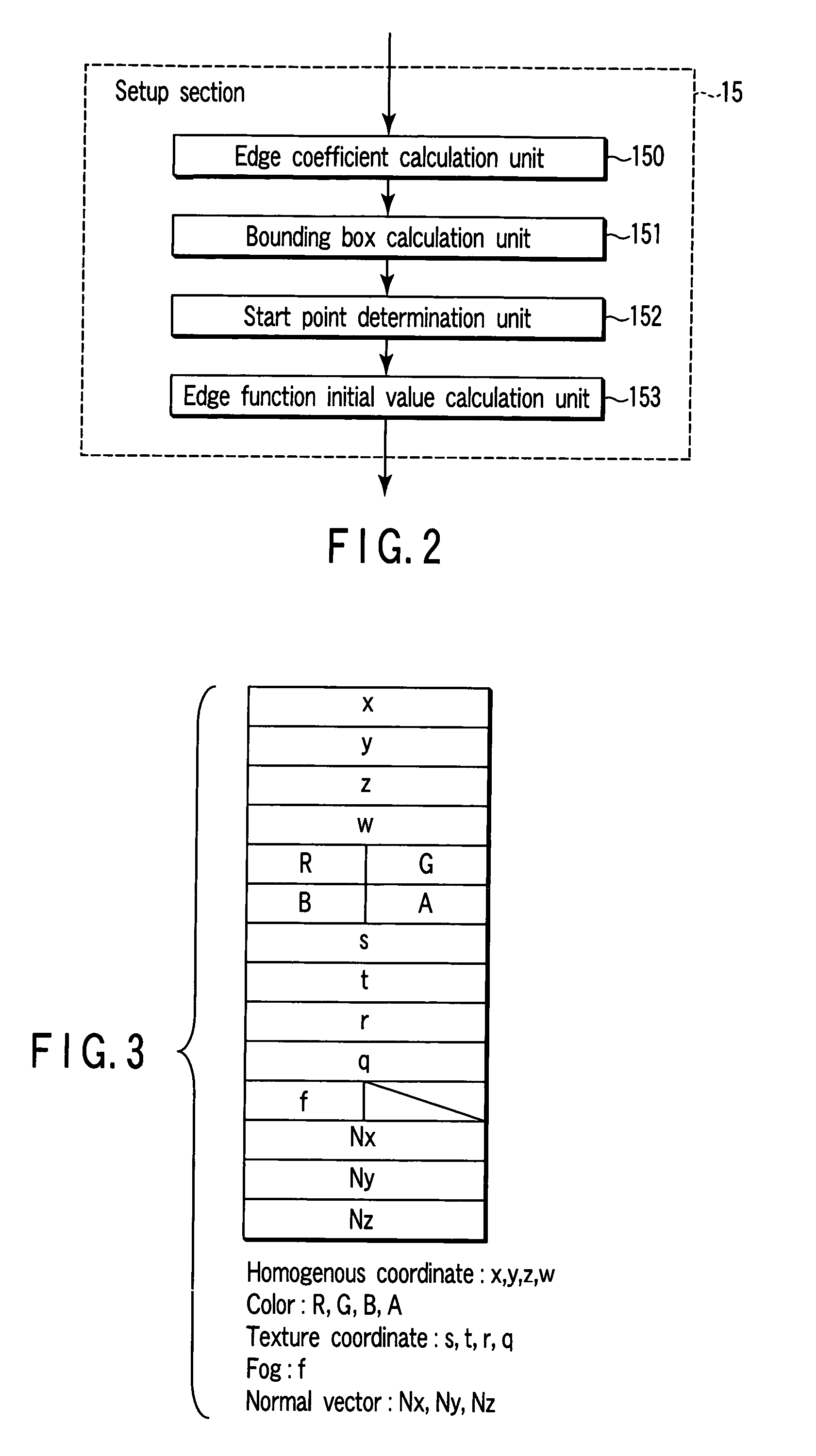
A setup section acquires vertex data including at least homogeneous coordinate and window coordinate relevant to two vertexes of rendering primitive, that is, segment. An edge coefficient calculation unit calculates an edge coefficient used for determining whether or not a pixel exists inside a projection area (parallelogram) of the segment. A bounding box calculation unit calculates a bounding box of the projection area from at least one vertex data of two vertexes and the edge coefficient. A start point determination unit classifies the projection area based on a combination of the edge coefficient, and determines scan start point and scan performing direction of the bounding box in accordance with the classification. An edge function initial value determination unit determines an edge function of the pixel corresponding to the scan start point as an initial value, and carries out a DDA, and thereby, generates setup data for rasterizing.

Description

CROSS-REFERENCE TO RELATED APPLICATIONS[0001]This application is based upon and claims the benefit of priority from prior Japanese Patent Application No. 2004-171258, filed Jun. 9, 2004, the entire contents of which are incorporated herein by reference.BACKGROUND OF THE INVENTION[0002]1. Field of the Invention[0003]The present invention relates to rendering apparatus (engine), rendering processing method and computer program product, which carry out rendering processing of a three-dimensional computer graphics (three-dimensional (3-D) CG) image. In particular, the present invention relates to rasterizing if rendering primitive includes a segment having a vertex existing backwardly from the viewpoint.[0004]2. Description of the Related Art[0005]Three-dimensional CG is a technique of representing and arranging various objects in a computer virtual three-dimensional space by modeling, and drawing how these objects are seen from viewpoints set in the space in a two-dimensional screen.[0...

Claims


Application Information

Patent Timeline
Patent Type & Authority Patents(United States)
IPC IPC(8): G06G5/00G06T15/00G09G5/00
CPCG06T15/40G06T15/30
Inventor KOKOJIMA, YOSHIYUKIBANDO, YOSUKE
Owner KK TOSHIBA
Learn More