Method of compressing values of a monitored electrical power signal

a technology of electrical power signal and compression ratio, which is applied in the field of power quality monitoring, can solve the problems of insufficient data, inability to determine the exact nature of problems, and inability to perform accurate calculations, etc., and achieve high compression ratio, accurate performance, and high compression ratio

Active Publication Date: 2008-08-19
ELSPEC LTD
View PDF10 Cites 8 Cited by
  • Summary
  • Abstract
  • Description
  • Claims
  • Application Information

AI Technical Summary

Benefits of technology

[0019]Optionally, the electrical power signal is represented by storing, for each harmonic, average values and respective numbers of consecutive cycles in which the harmonic has a value close to the average value. Although performing a Fourier transform is relatively processing intensive, the compression ratio achieved, and hence the ability to store power signals of long time periods, is considered advantageous.
[0020]In some embodiments of the invention, the length of the cycle of the power signal is continuously monitored (i.e., how close it is to the nominal 50 or 60 Hz), so that the Fourier transform is accurately performed on the signals of a cycle without skewing out of the cycle. In some embodiments of the invention, the rate of sampling of the power signals is adjusted according to the cycle length, so that each cycle has substantially the same number of samples, regardless of its length. Optionally, each cycle has a predetermined number of samples which is suitable for fast Fourier transformation (e.g., 256 samples).
[0021]By accurately following the cycles of the power signals, the harmonic values generally have the same or very similar values over long spans of signals. Thus, if only changes are stored, the compression achieves for normal electrical signals very high compression ratios (e.g., 1:10,000), which allow storage of large amounts of data.

Problems solved by technology

In some cases, however, on-line display of the waveforms and / or deduced parameters is not sufficient.
U.S. Pat. No. 6,675,071 to Griffin, Jr. et al., the disclosure of which is incorporated herein by reference, states that it would be desired to implement a power quality device that captures all the voltage waveform data at all times, but that such device is impracticable due to the large amounts of data involved.
This data, however, is not always sufficient to determine the exact nature of problems.

Method used


Image

  • Method of compressing values of a monitored electrical power signal
  • Method of compressing values of a monitored electrical power signal
  • Method of compressing values of a monitored electrical power signal

Examples


Embodiment Construction

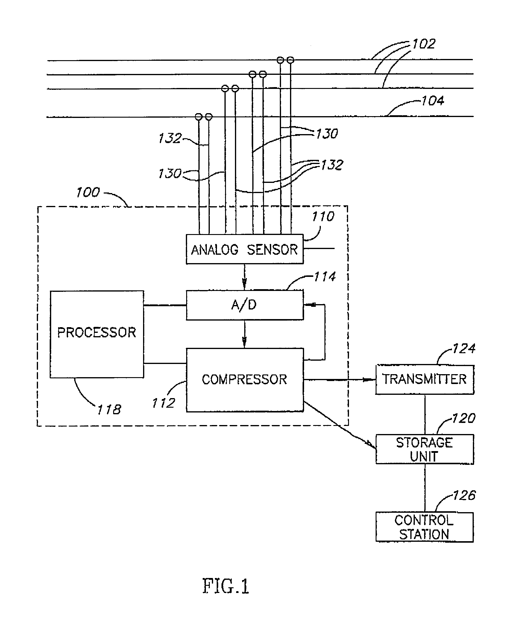
[0043]FIG. 1 is a schematic illustration of a compression unit 100, in accordance with an exemplary embodiment of the invention. Compression unit 100 optionally connects to electrical wires, for example to three phase lines 102 and a neutral line 104, to monitor the signals passing thereon, for quality monitoring. Compression unit 100 compresses the signals sensed from the electrical wires in order to allow storage of monitoring data for large durations, optionally continuously without relation to whether an event of interest was identified. In some embodiments of the invention, compression unit 100 includes current measurement connections 130 and voltage measurement connections 132. The connections may include physical connections, magnetic field connections and / or using any other coupling.

[0044]Compression unit 100 optionally includes an analog sensor 110 which senses the monitored signals, an A / D converter 114 which converts the sensed analog signals into digital samples, and a c...


PUM


Abstract

A method of compressing values of a waveform of a monitored electrical power signal. The method includes acquiring data representative of periods of the waveform, decomposing the waveform of the power signal into a plurality of components over a plurality of periods of the waveform, compressing the values of at least some of the components over a plurality of periods, and storing these values and extents.

Description

CROSS-REFERENCE TO RELATED APPLICATIONS[0001]This application is a National Phase Application of PCT International Application No. PCT / IL2004 / 000332, International Filing Date Apr. 18, 2004, the entire disclosure of which is hereby incorporated by reference.FIELD OF THE INVENTION[0002]The present invention relates to the field of power quality monitoring and particularly to storage for later reference of power quality data.BACKGROUND OF THE INVENTION[0003]In order to provide high quality electric power service, it is desired to monitor the quality of the electric signals at different locations along an electrical power network. Particularly it is desired to know the waveform of the current and voltage at various network locations at the time at which a specific event occurred (e.g., a blackout) in order to understand the cause of the event.[0004]U.S. Pat. No. 5,736,847 to Van Doom et al., the disclosure of which is incorporated herein by reference, describes a power meter for readin...

Claims


Application Information

Patent Timeline
Patent Type & Authority Patents(United States)
IPC IPC(8): G01R13/00G06F17/00G01R11/32G01R13/02G01R19/25G01R21/00G01R21/06G01R21/133G01R23/16G01R23/18
CPCG01R13/0209G01R19/2513G01R21/1331G01R23/16G01R21/06G01R21/006G01R23/18
Inventor NISENBLAT, POLBROSHI, AMIR MORDEHAYEFRATI, OFIR
Owner ELSPEC LTD
Why Eureka
Try Eureka