Fuel injection control apparatus designed to minimize combustion noise of engine

a technology of fuel injection control and engine combustion noise, which is applied in mechanical devices, electric control, machines/engines, etc., can solve the problems of reducing the quantity of fuel and the reduction of the combustion noise of the engine, so as to reduce the charge-up voltage, reduce the amount of heat, and ensure the stability of operation of the diesel engine

Inactive Publication Date: 2008-08-26
DENSO CORP
View PDF8 Cites 14 Cited by
  • Summary
  • Abstract
  • Description
  • Claims
  • Application Information

AI Technical Summary

Benefits of technology

[0009]It is another object of the invention to provide a fuel injection control apparatus designed to increase the number of injections of fuel into an engine in each operating cycle of the engine based on the temperature of an injector drive circuit to reduce the combustion noise of the engine.
[0010]According to one aspect of the invention, there is provided a fuel injection control apparatus which may be employed in automotive common rail diesel engines. The fuel injection control apparatus for a diesel engine comprises: (a) an accumulator in which fuel is stored at a controlled pressure; (b) an electrically energized injector working to inject the fuel, as stored in the accumulator, into a diesel engine; (c) an injector drive circuit working to control energization of the injector; and (d) a controller working to determine a multi-injection mode in which the fuel is to be injected from the injector into the diesel engine in a sequence of multiple injections in an operating cycle of the diesel engine and output an injection signal to the injector drive circuit to perform the multi-injection mode through the injector. The controller determines whether the number of injections to be executed in a subsequent operating cycle of the diesel engine is allowed to be increased or not in a range which ensures stability of operation of the diesel engine based on the temperature of the injector drive circuit. When it is determined that the number of injections is allowed to be increased, the controller increases the number of injections to be executed in the subsequent operating cycle of the engine. This results in a decrease in quantity of fuel to be sprayed in each of the injections without increasing the temperature of the injector drive circuit undesirably, which leads to a reduction in combustion noise of the engine.
[0015]When it is determined that the number of injections to be executed in the subsequent operating cycle of the diesel engine is not allowed to be increased, the controller may decrease the number of injections to be executed in the subsequent operating cycle of the diesel engine.
[0016]After execution of the multi-injection mode, the controller may determine whether the diesel engine is in an instable operating condition or not. When it is determined that the diesel engine is in the instable operating condition, the controller may decrease or prohibit the number of injections to be executed in the subsequent operating cycle of the diesel engine from being increased.
[0017]The injector drive circuit includes a valve-opening current supply circuit equipped with a capacitor and a valve position-holding current supply circuit. When it is required to open the injector, the valve-opening current supply circuit works to release electrical energy from the capacitor to supply a valve opening current to the injector. The valve position-holding current supply circuit works to supply a valve position-holding current after supply of the valve opening current to hold the injector at a given valve position. The controller decreases charge-up voltage for charging the capacitor of the valve-opening current supply circuit within a range which ensures the stability of operation of the diesel engine. This results in a decrease in amount of heat arising from charging and discharging of the capacitor, thus allowing the number of injections to be increased further, which leads to a further reduction in the combustion noise of the engine.

Problems solved by technology

This results in a decrease in quantity of fuel to be sprayed in each of the injections without increasing the temperature of the injector drive circuit undesirably, which leads to a reduction in combustion noise of the engine.

Method used


Image

  • Fuel injection control apparatus designed to minimize combustion noise of engine
  • Fuel injection control apparatus designed to minimize combustion noise of engine
  • Fuel injection control apparatus designed to minimize combustion noise of engine

Examples


first embodiment

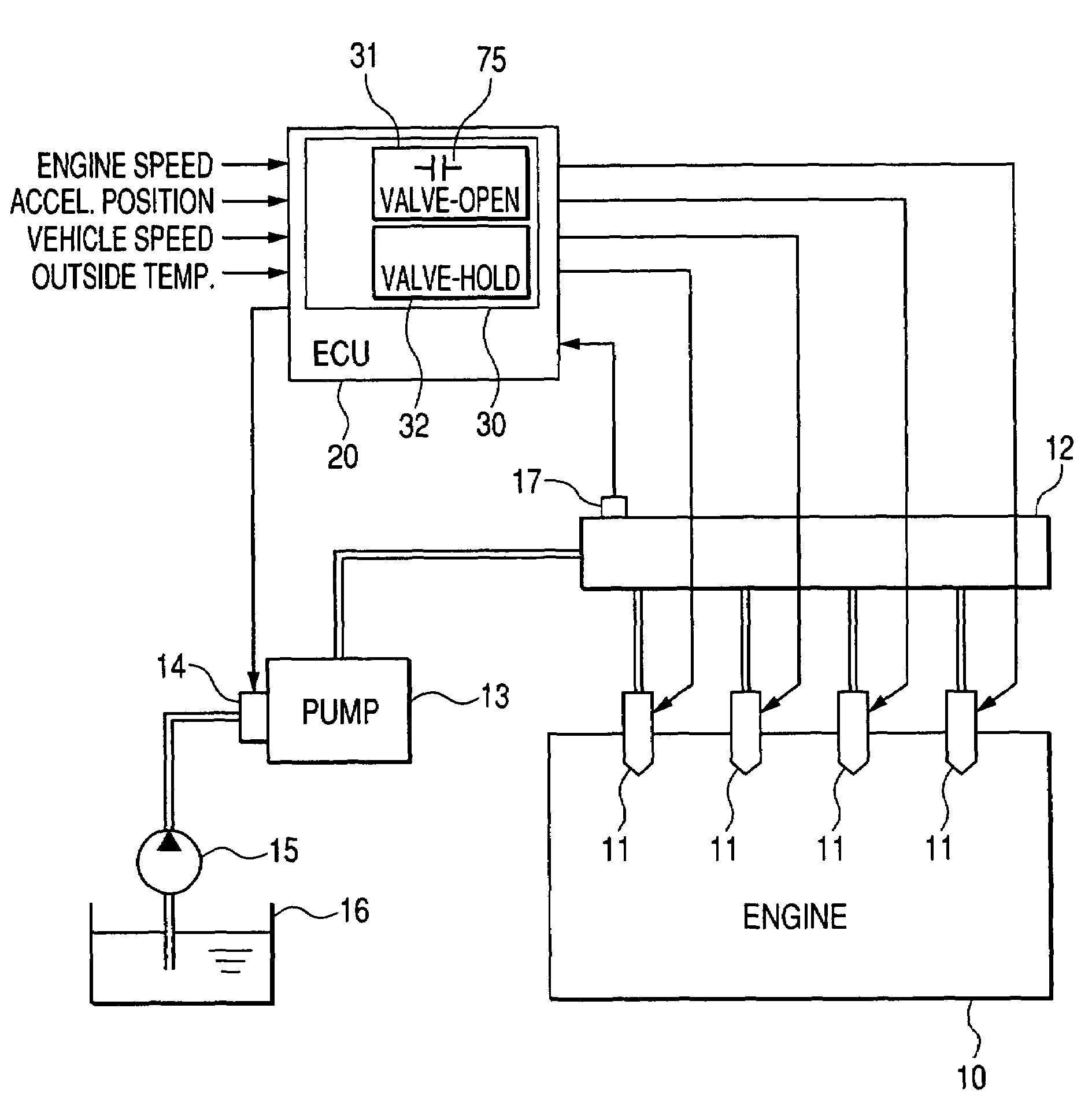
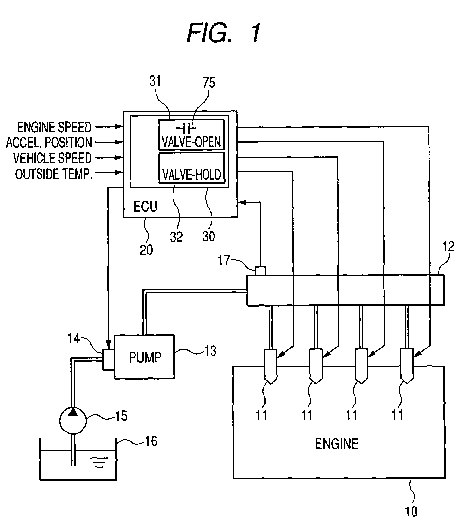
[0029]Referring to the drawings, wherein like reference numbers refer to like parts in several views, particularly to FIG. 1, there is shown a fuel injection control apparatus engineered as a common rail injection system according to the invention which is designed for a multi-cylinder diesel engine to be mounted in automotive vehicles.

[0030]The common rail injection system includes solenoid-operated fuel injectors 11 one for each cylinder of a four-cylinder diesel engine 10, a common rail 12, a high-pressure pump 13, a suction control pump 14, a feed pump 15, a fuel pressure sensor 17, and an electronic control unit (ECU) 20. The fuel injectors 11 are each connected to the common rail 12. The high-pressure fuel pump 13 is connected to the common rail 12 and equipped with the suction control valve 14. The suction control valve 14 is connected to a fuel tank 16 through the feed pump 15. The feed pump 15 works to pump fuel out of the fuel tank 16 and feed it to the suction control val...

second embodiment

[0055]The common rail injection system according to the invention will be described below which is designed to optimize the charge-up voltage for the valve-opening current supply circuit 31 of the injector drive circuit 30 to decrease the amount of heat generated in the injector drive circuit 30 in order to maximize the number of injection events in a subsequent operating cycle of the engine 10.

[0056]The charge-up voltage for the capacitor 75 of the valve-opening current supply circuit 31 is selected to be high enough to ensure the stability in opening each of the fuel injectors 11 even in the case where a variation in characteristics among solenoids of the fuel injectors 11, the resistance of harnesses leading to the fuel injectors 11, and the temperature of outside air are in the worst conditions. The ECU 20 is designed to decrease the charge-up voltage within a range which ensures the stability of operating conditions of the engine 10 to minimize the amount of heat, as generated ...


PUM


Abstract

A fuel injection control apparatus for a diesel engine is provided which works to determine the number of a sequence of injection events to inject fuel into the engine in each operating cycle of the engine and increase it based on the temperature of an injector drive circuit. When the temperature of the injector drive circuit is relatively low, the apparatus increases the number of injection events to decrease the degree of combustion in the engine, thereby reducing the combustion noise of the engine.

Description

CROSS REFERENCE TO RELATED DOCUMENT[0001]The present application claims the benefit of Japanese Patent Application No. 2006-110462 filed on Apr. 13, 2006, the disclosure of which is totally incorporated herein by reference.BACKGROUND OF THE INVENTION[0002]1. Technical Field of the Invention[0003]The present invention relates generally to a fuel injection control apparatus, such as a common rail system for automotive diesel engines, which is designed to inject fuel into a cylinder of an internal combustion engine through a sequence of multiple injection events in each operating cycle of the engine, and more particularly, to such an apparatus deigned to increase the number of injection events to minimize a combustion noise of the engine.[0004]2. Background Art[0005]Typical diesel engines for automotive vehicles to required not only to meet tightened exhaust regulations, but also to reduce noise arising from combustion of the engine which is usually higher than that in gasoline engines...

Claims


Application Information

Patent Timeline
Patent Type & Authority Patents(United States)
IPC IPC(8): F02B3/00F02M1/00
CPCF02D41/20F02D41/2451F02D41/402F02D41/2467Y02T10/44F02D2041/2006F02D2041/2065F02M63/0225F02D2041/2003Y02T10/40
Inventor BAN, MITSURU
Owner DENSO CORP
Why Eureka
Try Eureka