Control system for pre-mixture compression-ignition engine

a control system and engine technology, applied in the direction of electric control, ignition automatic control, machines/engines, etc., can solve the problems of combustion noise exceeding an allowable value, combustion noise caused by compression ignition, and relatively loud combustion noise, so as to reduce combustion noise

Active Publication Date: 2019-02-28
MAZDA MOTOR CORP
View PDF0 Cites 7 Cited by
  • Summary
  • Abstract
  • Description
  • Claims
  • Application Information

AI Technical Summary

Benefits of technology

[0005]The present disclosure is made in view of the above situations and aims to perform combustion by compression ignition while reducing combustion noise of a pre-mixture compression-ignition engine below an allowable value.

Problems solved by technology

Incidentally, combustion caused by compression ignition accompanies relatively loud combustion noise.
For example, if such a combustion is to be performed while an engine is operating within a high load range including a full load, the combustion noise may exceed an allowable value.

Method used


Image

  • Control system for pre-mixture compression-ignition engine
  • Control system for pre-mixture compression-ignition engine
  • Control system for pre-mixture compression-ignition engine

Examples


Embodiment Construction

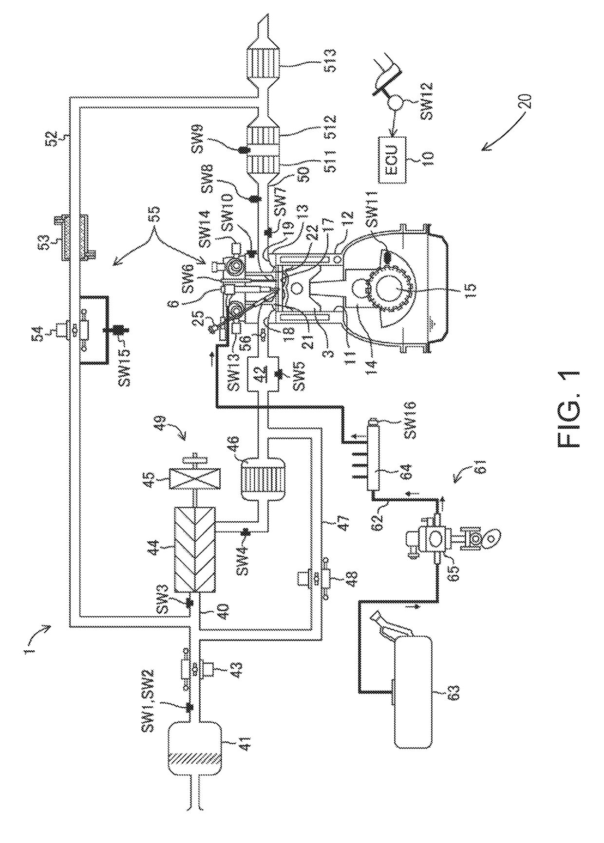
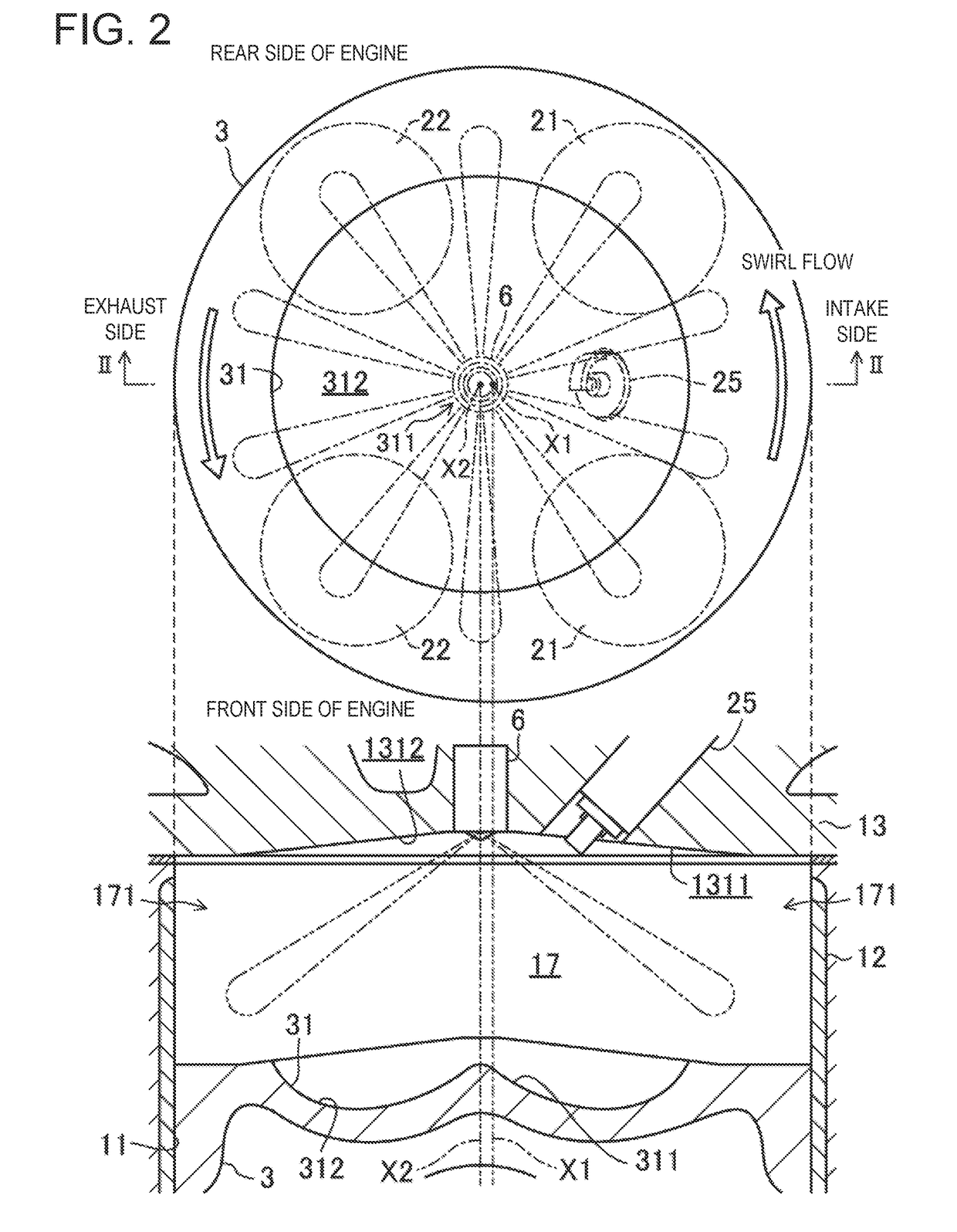
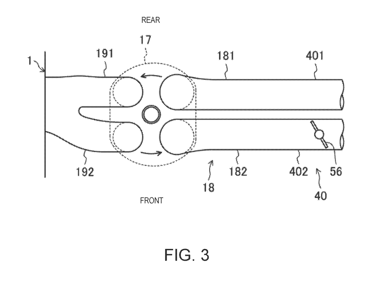
[0062]Hereinafter, one embodiment of a control system for a pre-mixture compression-ignition engine is described in detail with reference to the accompanying drawings. The following description gives one example of the control system for an engine. FIG. 1 is a diagram illustrating a configuration of the engine. FIG. 2 is a diagram illustrating a structure of a combustion chamber, in which the upper part is a plan view of the combustion chamber and the lower part is an II-II cross-sectional view. FIG. 3 is a plan view illustrating structures of the combustion chamber and an intake system. Note that in FIG. 1, an intake side is on the left side and an exhaust side is on the right side of the drawing sheet. Further in FIGS. 2 and 3, the intake side is on the right side and the exhaust side is on the left side of the drawing sheets. FIG. 4 is a block diagram illustrating a configuration of the control device for the engine.

[0063]An engine 1 is a four-stroke engine which is operated by a...


PUM


Abstract

A control system for a pre-mixture compression-ignition engine is provided, configured such that in a first combustion mode, the control unit controls the fuel injection valve to have a fuel amount within a mixture gas in an outer circumferential portion of the combustion chamber larger than in the center portion, the swirl generating part to generate a swirl flow in the outer circumferential portion, and the spark plug to ignite the mixture gas in the center portion. In a second combustion mode, the control unit controls the fuel injection valve to start a fuel injection on intake stroke so that the mixture gas is formed in the entire combustion chamber, the swirl generating part so that a swirl flow becomes weaker than in the first combustion mode, and the spark plug to ignite the mixture gas before CTDC.

Description

TECHNICAL FIELD[0001]The present disclosure relates to a control system for a pre-mixture compression-ignition engine.BACKGROUND OF THE DISCLOSURE[0002]JP4082292B discloses an engine in which a mixture gas inside a combustion chamber is combusted by compression ignition within a given operating range of the engine in which an engine load and an engine speed are low. In this engine, the mixture gas combusts by spark-ignition within an operating range in which the engine load is higher than the given operating range and an operating range in which the engine speed is higher than the given operating range. In this engine, also within the given operating range, a spark plug performs the spark-ignition near a top dead center of compression stroke to stimulate compression ignition of the mixture gas.[0003]JP5447435B discloses an engine in which the mixture gas inside a combustion chamber is combusted by compression ignition within a high load range of the engine. In this engine, within a ...

Claims


Application Information

Patent Timeline
Patent Type & Authority Applications(United States)
IPC IPC(8): F02D41/30F02B1/14F02B11/00F02B23/06F02B23/10
CPCF02D41/3041F02B1/14F02B11/00F02B23/0624F02B23/10F02D41/3076F02B2023/108F02B31/06F02D9/10F02D41/0002F02D41/3035F02D41/3064F02D41/401F02D41/402F02P5/15F02D41/3029F02D41/3047F02D2041/0015F01B11/02F01B1/10F02B23/101F02B31/085F02B2031/006Y02T10/12Y02T10/40
Inventor YAMAGUCHI, NAOHIROMORIMOTO, HIROKIMIYAMOTO, TORUNOOMO, AKIRA
Owner MAZDA MOTOR CORP
Why Eureka
Try Eureka