
Synthesis decoding and methods of use thereof

a synthesis and image technology, applied in the field of decoding images, can solve the problems of difficult image restoration, large and unrealistic value assigned, and inability to use inverse filters

Active Publication Date: 2008-08-26
HAND HELD PRODS
View PDF41 Cites 49 Cited by
  • Summary
  • Abstract
  • Description
  • Claims
  • Application Information

AI Technical Summary

Benefits of technology

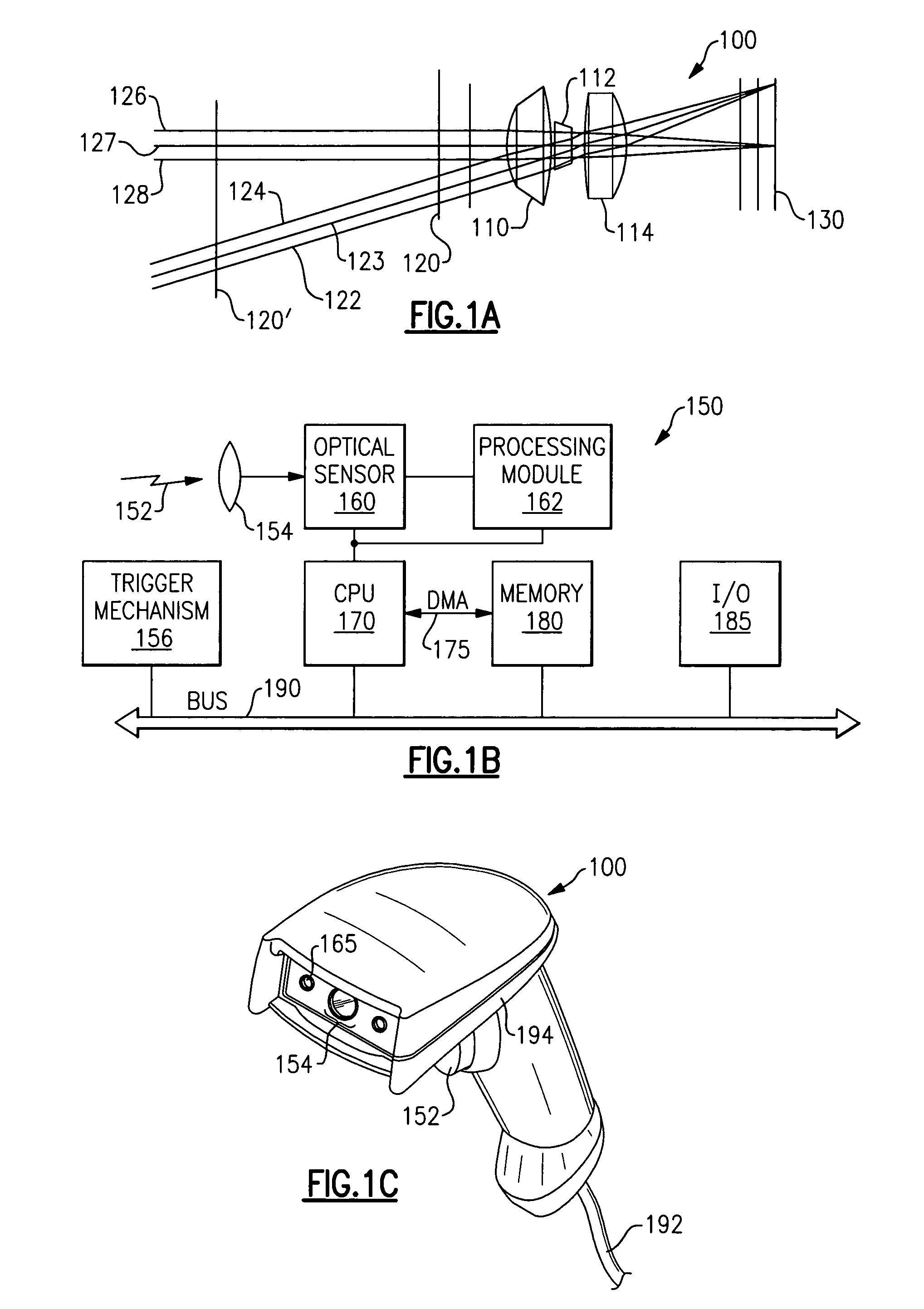
[0010]In one aspect, the invention relates to an optical reader for reading an image. The optical reader comprises an optical sensor for receiving light corresponding to an image of interest, and for providing an electrical signal encoding information representative of at least a portion of the image of interest; an optical lens system in optical communication with the optical sensor, the optical lens system having a minimum working distance corresponding to a shortest distance between the optical sensor and the image of interest at which distance the image is at the convolution limited depth of field (clDOF) at the optical sensor, the optical lens system having a maximum working distance corresponding to a longest distance between the optical sensor and the image of interest at which distance the image is at the pixel limited depth of field (plDOF) at the optical sensor; and a memory containing a representation of an electrical signal encoding information representative of at least a portion of the image of interest, the representation of the electrical signal calculated to be produced by the optical sensor when the image of interest is situated at a distance selected from one of a distance shorter than the minimum working distance and a distance longer than the maximum working distance. When the optical sensor operates at a selected one of a distance shorter than the minimum working distance and a distance longer than the maximum working distance, the optical reader successfully decodes the information encoded in the electrical signal by comparing the corresponding representation of an electrical signal contained in the memory with the electrical signal provided from the optical sensor.

Problems solved by technology

Image restoration has been proven to be a difficult problem.
As a general rule, the use of inverse filters is not practical because they are highly susceptible to noise.
The inverse function of a point having a very small value is assigned a very large and unrealistic value that tends to distort the reconstructed image.
However, if some of the data is corrupted, or is missing, the application of a least squares fitting method will provide a solution that is influenced by the corrupted data, or that fails to take into account the missing data.
In either event, the “best fit” solution can be seriously in error as compared to an analysis of data that is complete and uncorrupted.
As indicated, a number of problems in decoding corrupted, distorted or incomplete image data representing symbols such as barcodes have been observed.

Method used


Image

  • Synthesis decoding and methods of use thereof
  • Synthesis decoding and methods of use thereof
  • Synthesis decoding and methods of use thereof

Examples


Embodiment Construction

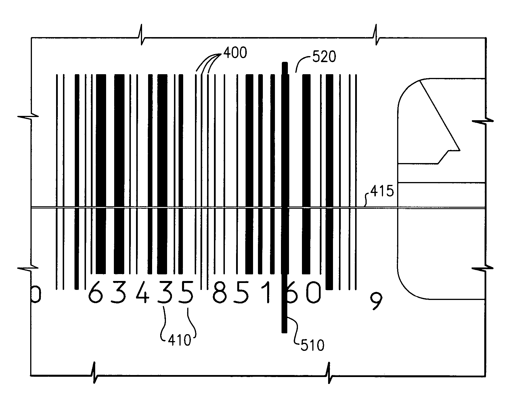
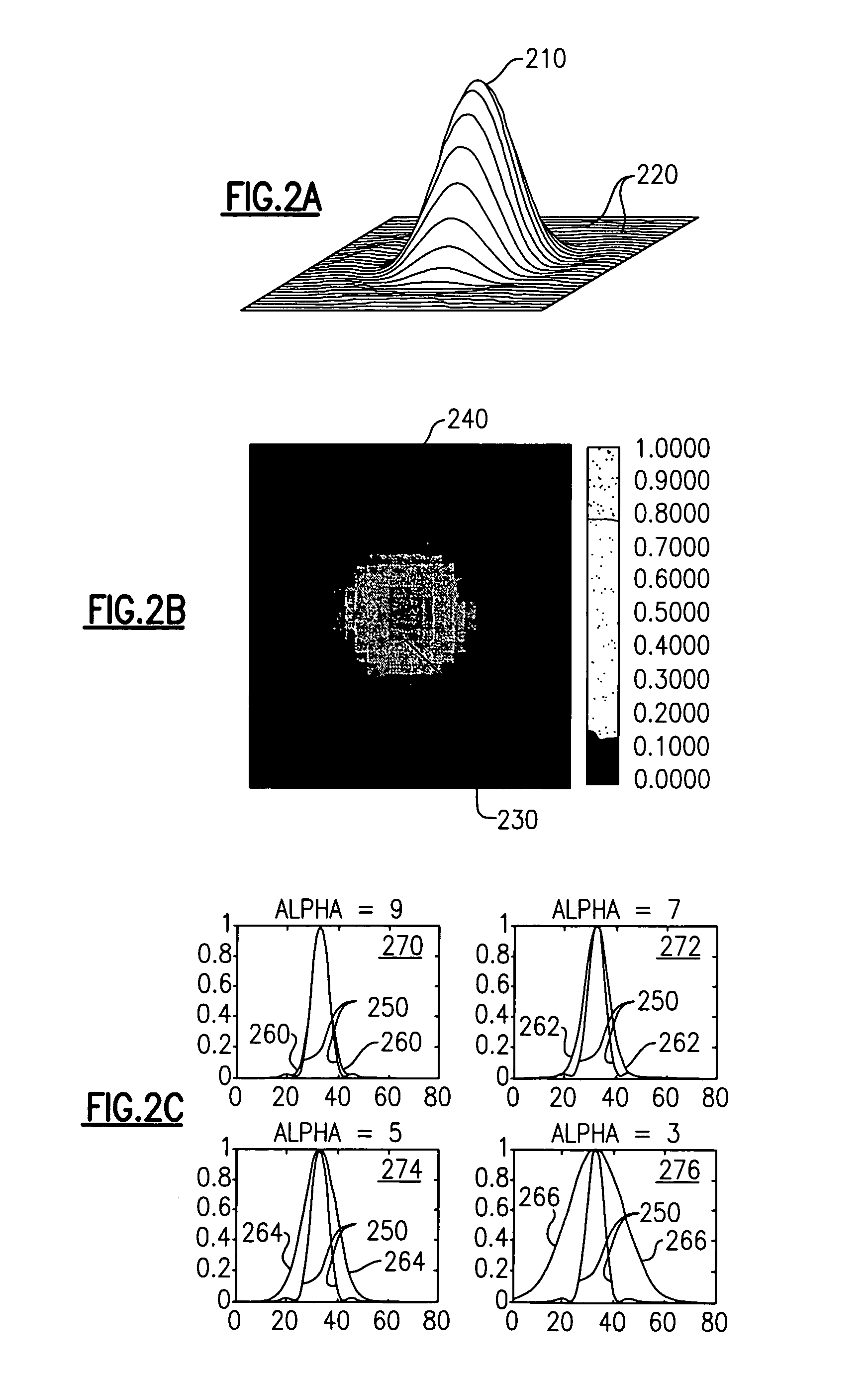
[0030]The present invention provides systems and methods for decoding optical indicia, such as barcodes, which are physically situated beyond the designed limits of the depth of field of a reader or imager, or which are degraded with respect to valid optical indicia. As will be explained in greater detail below, an imager or reader that is used to “read” an indicium such as a barcode at a position farther away than the designed distant depth of field limit, or which has been degraded, will obtain a distorted signal. In similar manner, a reader that is used to “read” an indicium at too close a distance, or at a distance less than the designed near depth of field limit, will observe a truncated signal (e.g., will see only a portion of the indicium at one time, much as if one viewed a scene through a keyhole). In either circumstance, using conventional decoding systems and methods, the reader will in most situations fail to provide a suitable decoded signal, and often will simply repor...


PUM


Abstract

Systems and methods for successfully decoding optical images of objects of interest when such objects are situated outside a conventional working range of an imaging system, or when such objects are degraded. The systems and methods are based upon a comparison of computed signals corresponding to distorted images that would be obtained from known objects, such as barcodes, when viewed outside a working range, or when degraded, with actual signals obtained from the object of interest. The computed signals in one embodiment are recorded in a lookup table. An advantage of the systems and methods disclosed is that there results a smooth, monotonic probability of correctly decoding the image of interest, even beyond the working distance. A handheld or portable apparatus useful for practicing the invention is also disclosed.

Description

CROSS REFERENCE TO RELATED APPLICATIONS[0001]This application is related to co-pending U.S. patent application Ser. No. 11 / 077,975, filed Mar. 11, 2005, entitled “Bar Code Reading Device With Global Electronic Shutter Control,” and to co-pending U.S. patent application Ser. No. 10 / 958,779, filed Oct. 5, 2004, entitled “System And Method To Automatically Discriminate Between A Signature And A Barcode,” which applications are incorporated herein by reference in their entirety.FIELD OF THE INVENTION[0002]The invention relates to decoding images in general and particularly to a system and method for decoding images that operates beyond a conventional depth of field of a viewing system.BACKGROUND OF THE INVENTION[0003]Image restoration has been proven to be a difficult problem. There are several techniques that have been proposed for the recovery of images, including images of symbols such as barcodes. Proposed methods include inverse filtering, least squares (Wiener) filtering, and iter...

Claims


Application Information

Patent Timeline
Patent Type & Authority Patents(United States)
IPC IPC(8): G02B26/10G06K7/10G06K9/22
CPCG06K7/1093
Inventor WANG, YNJIUN P.LONGACRE, JR., ANDREW
Owner HAND HELD PRODS
Learn More