Multidirectionally compliant fastening system

a multi-directional, compliant technology, applied in the direction of rod connection, ring spring, coupling, etc., can solve the problems of high temperature and heavy vibration, damage to many materials used, and limited types of materials that can be used

Inactive Publication Date: 2008-08-26
SIEMENS ENERGY INC
View PDF22 Cites 65 Cited by
  • Summary
  • Abstract
  • Description
  • Claims
  • Application Information

AI Technical Summary

Benefits of technology

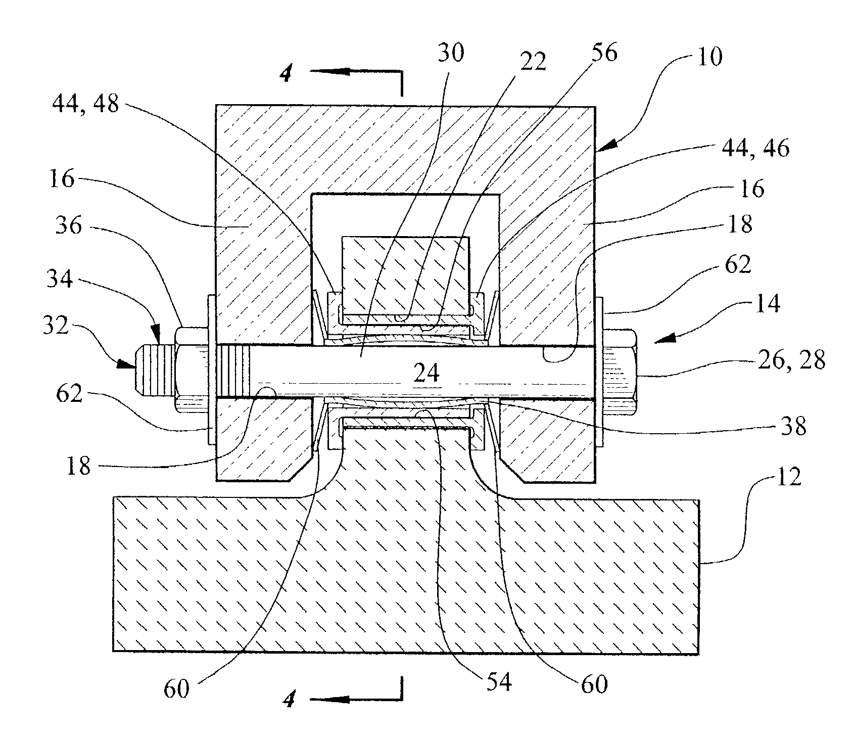
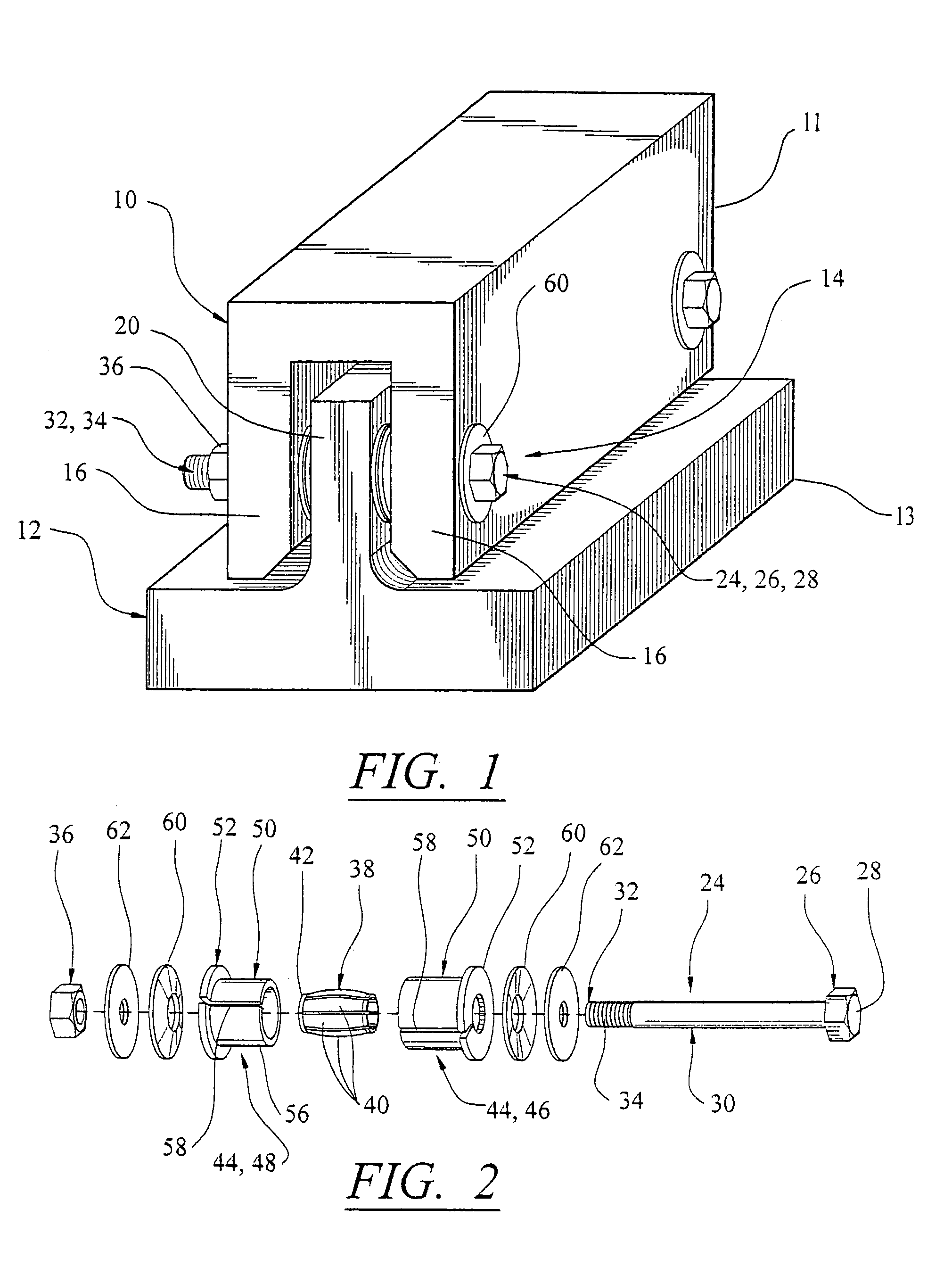
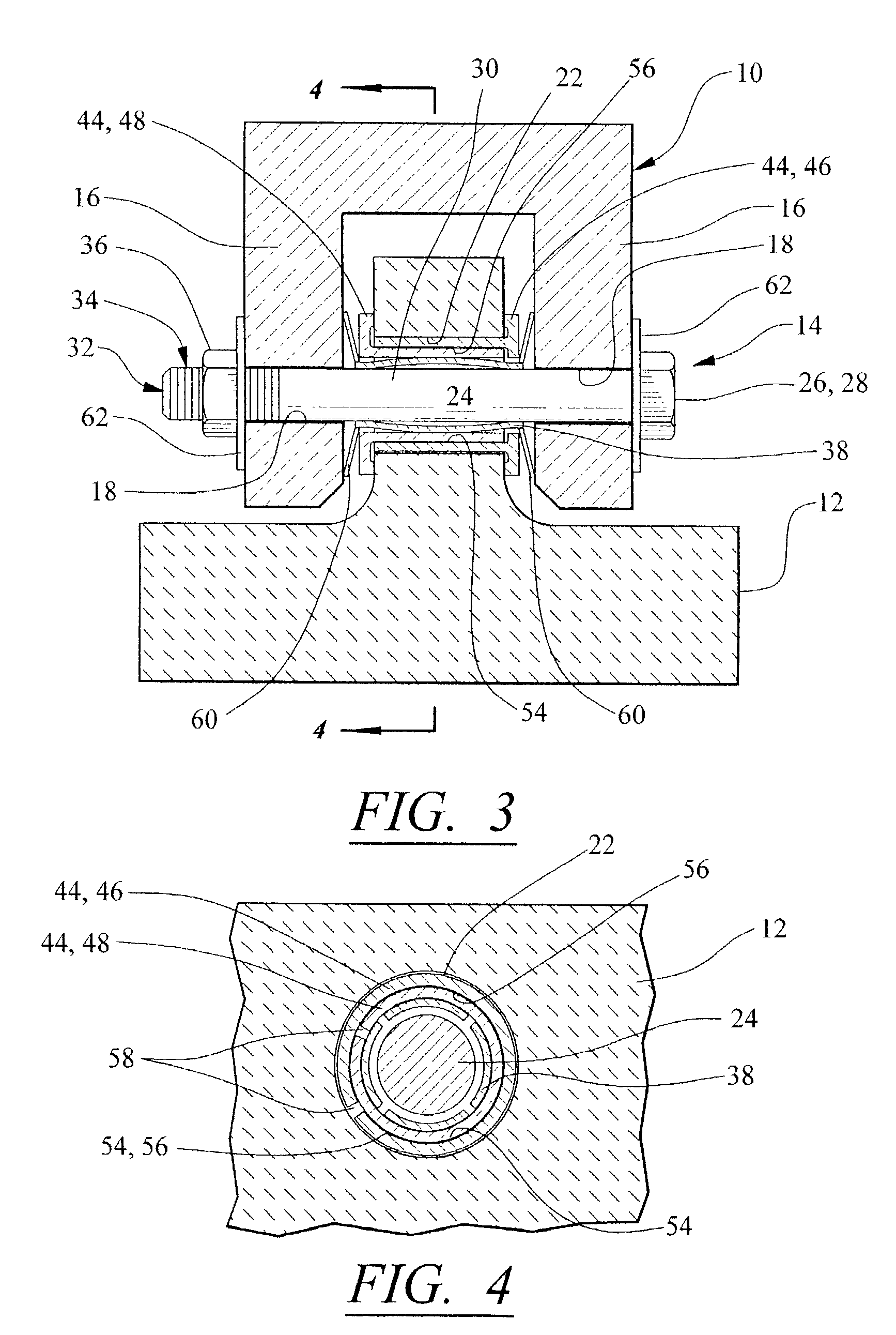
[0011]In still another aspect, a multi-directionally compliant fastening system is used to join a ceramic structure having an opening and a clevis having a set of opposing openings. The opening in the ceramic structure is positioned between and in alignment with the set of opposing openings in the clevis. The aligned openings receive at least a portion of a fastener assembly. The fastener assembly includes a bolt, a nut, flat washers, spring washers, a split bushing and a spring bushing. The spring bushing is at least partially enclosed within the split bushing. The split bushing and spring bushing are at least partially disposed within the opening in the ceramic structure. The spring washers are positioned between the aligning openings of the clevis and the ceramic structure. The bolt extends axially through the aligning openings of the clevis and ceramic structure. The bolt has opposing ends with a head at one end and the nut is secured to the other end of the bolt. A flat washer is disposed between the head of the bolt and the clevis and also between the nut and the clevis.

Problems solved by technology

Gas turbines typically produce high temperatures and heavy vibrations during operation, and these conditions can be damaging to many materials used in the construction of the turbines.
Consequently, the types of materials that can be used is quite limited.
Unfortunately, ceramics can be relatively brittle, especially when used as structural components.
When fastening ceramic materials to other structures, great care must be taken because these ceramic materials may be intolerant to local stresses introduced by a fastener.
Eventually, the metal fastener may come into contact with the surrounding ceramic, applying potentially cracking forces.

Method used


Image

  • Multidirectionally compliant fastening system
  • Multidirectionally compliant fastening system
  • Multidirectionally compliant fastening system

Examples


Embodiment Construction

[0016]The fastening system of the present invention provides axial and radial compliance and is preferably used for joining two dissimilar materials, particularly those materials having substantially different coefficients of thermal expansion. The fastening system can be used in a variety of applications, where vibrational absorption is required along multiple axes of contact between two joined structures. For example, the fastening system of the invention can be used when one of the structures is relatively brittle and subject to cracking if subject to the vibrational loads of the other structure to which it is joined. Such constructions can occur in gas turbines, furnaces and coal burners, in which ceramic materials are used for their high temperature toleration and are supported by metal structures in vibrational environments. Also, aspects of the present invention address differences in thermal expansion which can result in fracturing forces upon the ceramic or other brittle st...


PUM

PropertyMeasurementUnit
resilient complianceaaaaaaaaaa
coefficient of thermal expansionaaaaaaaaaa
coefficients of thermal expansionaaaaaaaaaa

Abstract

A fastening system has at least one peripheral spring and at least one peripherally expandable bushing, with the peripheral spring being at least partially enclosed within the peripherally expandable bushing. The peripheral spring and peripherally expandable bushing each contain axial openings for receiving an elongated fastening member to secure two dissimilar structures together. The peripheral spring can be a spring bushing. The spring bushing can comprise a series of radially outwardly bowed ribs joined at one end by a fixed hoop. The axial spring can be a spring washer. The peripherally expandable bushing can be a split bushing.

Description

CROSS REFERENCE TO RELATED APPLICATIONS[0001](Not Applicable)STATEMENT REGARDING FEDERALLY SPONSORED RESEARCH[0002](Not Applicable)FIELD OF THE INVENTION[0003]The present invention relates in general to fastening systems and, more particularly, to fastening systems for joining dissimilar materials.BACKGROUND OF THE INVENTION[0004]Gas turbines typically produce high temperatures and heavy vibrations during operation, and these conditions can be damaging to many materials used in the construction of the turbines. Consequently, the types of materials that can be used is quite limited. For example, suitable materials must have high-strength and low-weight characteristics while at the same time be able to withstand high temperatures. Engineers have considered certain metal alloys, composites and ceramics among the materials to be used in such an environment.[0005]Ceramics have been considered because of their comparatively light weight and high melting points. Unfortunately, ceramics can...

Claims


Application Information

Patent Timeline
Patent Type & Authority Patents(United States)
IPC IPC(8): F16F1/00C04B37/02F16B1/00F16B5/02
CPCF16B5/0241F16B2001/0085Y10T403/75Y10T403/32991Y10T403/217F16B2200/85
Inventor NORTH, DAVID D.
Owner SIEMENS ENERGY INC
Why Eureka
Try Eureka