Gas turbine engine exhaust nozzle including an infrared suppression system having a plurality of U-shaped blocking fins and method of assembling said exhaut nozzle

a gas turbine engine and exhaust nozzle technology, which is applied in the manufacture of engines, hot gas positive displacement engine plants, machines/engines, etc., to achieve the effect of suppressing the infrared signature of exhaus

Active Publication Date: 2008-09-02
GENERAL ELECTRIC CO
View PDF29 Cites 3 Cited by
  • Summary
  • Abstract
  • Description
  • Claims
  • Application Information

AI Technical Summary

Benefits of technology

[0007]In another aspect, an exhaust assembly for a gas turbine engine is provided. The exhaust assembly includes an engine exhaust nozzle coupled to the gas turbine engine, an exhaust duct at least partially circumscribing the engine exhaust nozzle such that a cooling passage is defined between the engine exhaust nozzle and the exhaust duct, and an infrared suppression system coupled to the engine exhaust nozzle, the infrared suppression system comprising a substantially U-shaped cross-sectional profile that extends at least partially into the cooling passage, the suppression system facilitates suppressing an exhaust infrared signature of the gas turbine engine.
[0008]In a further aspect, a gas turbine engine is provided. The gas turbine engine includes an engine exhaust nozzle coupled to the gas turbine engine, an exhaust duct at least partially circumscribing the engine exhaust nozzle such that a cooling passage is defined between the engine exhaust nozzle and the exhaust duct, an infrared suppression system coupled to the engine exhaust nozzle, the infrared suppression system comprising a substantially U-shaped cross-sectional profile that extends at least partially into the cooling passage, the suppression system facilitates suppressing an exhaust infrared signature of the gas turbine engine, and a plurality of cooling fins coupled to the engine exhaust nozzle axially forward of the infrared suppression system.

Problems solved by technology

However, at least one known infrared suppression system actually absorbs heat that is emitted from the gas turbine exhaust thus increasing a temperature of the infrared suppression system itself.

Method used


Image

  • Gas turbine engine exhaust nozzle including an infrared suppression system having a plurality of U-shaped blocking fins and method of assembling said exhaut nozzle
  • Gas turbine engine exhaust nozzle including an infrared suppression system having a plurality of U-shaped blocking fins and method of assembling said exhaut nozzle
  • Gas turbine engine exhaust nozzle including an infrared suppression system having a plurality of U-shaped blocking fins and method of assembling said exhaut nozzle

Examples


Embodiment Construction

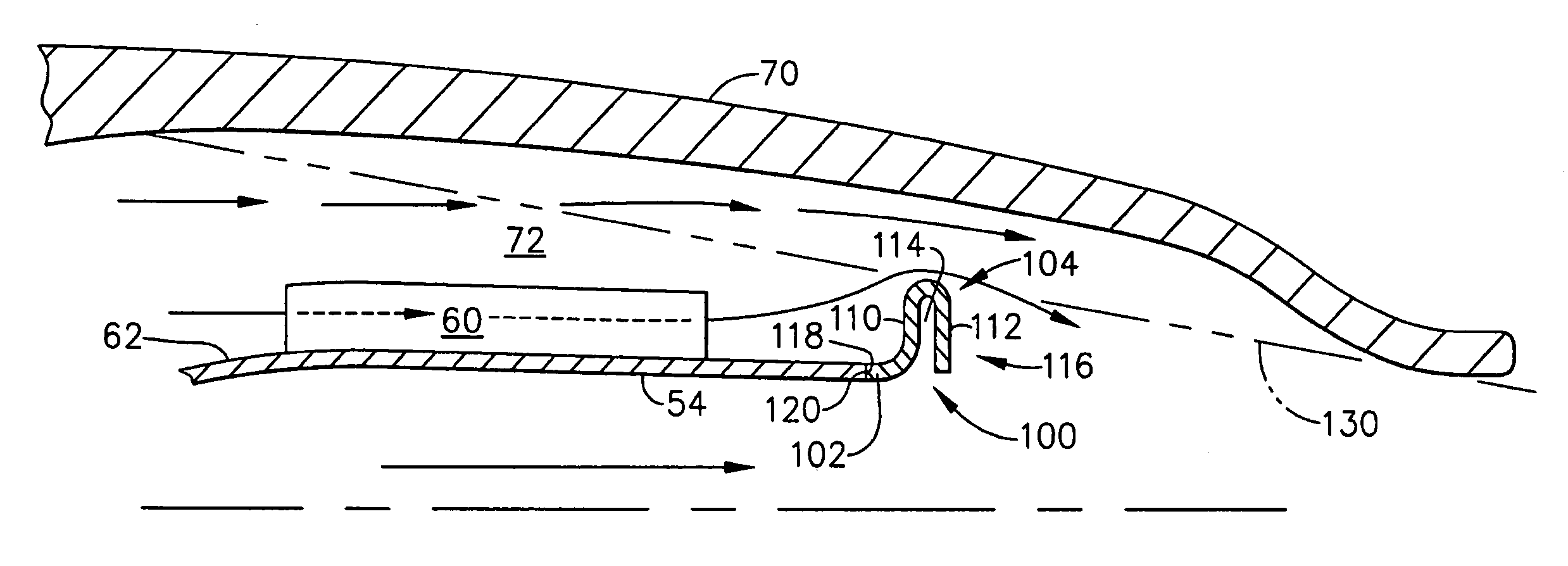
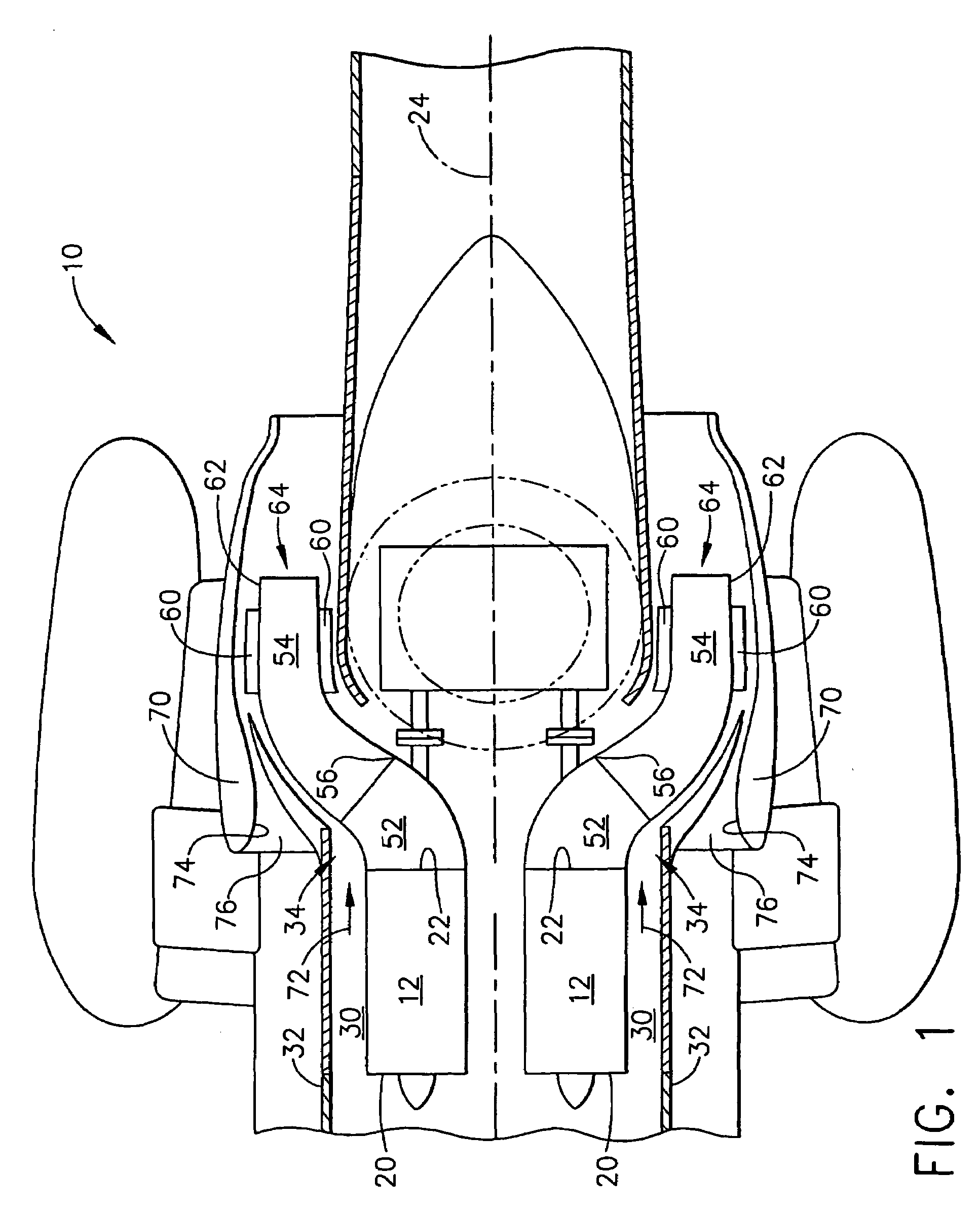
[0017]FIG. 1 is a plan view of an exemplary helicopter 10 that includes a pair of core gas turbine engines 12 that each include an inlet end 20 and an exhaust end 22. In the exemplary embodiment, gas turbine engines 12 are substantially symmetrical with respect to an axis of symmetry 24 extending between gas turbine engines 12. Gas turbine engines 12 are each mounted within an engine compartment 30 defined by a helicopter fuselage 32. Specifically, in the exemplary embodiment, each gas turbine engine 12 includes an exhaust assembly 34 that extends downstream from gas turbine engines 12 for discharging exhaust gases from gas turbine engines 12. In one embodiment, each gas turbine engine 12 is a T58, T64, T700 or CT7 gas turbine engine commercially available from General Electric Aircraft Engines, Lynn, Mass.

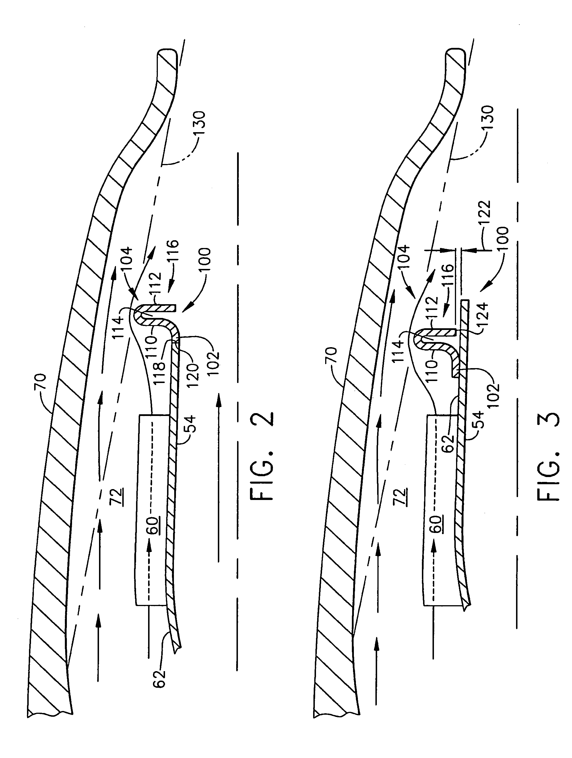
[0018]The infrared suppression systems described herein facilitate suppressing an exhaust infrared signature of each gas turbine engine 12 during engine operation, and / or post eng...


PUM


Abstract

A method for assembling a gas turbine engine includes mounting a core engine to a vehicle, coupling a fuselage radially outward and around the core engine, coupling an exhaust nozzle to the core engine to channel exhaust gases discharged from the core engine, wherein the exhaust nozzle includes a cowl and a primary nozzle coupled radially inward from the cowl, and coupling an infrared suppression system in flow communication with the engine exhaust nozzle to facilitate suppressing an exhaust infrared signature of the core engine, wherein the infrared suppression system includes a blocking fin having a substantially U-shaped cross-sectional profile and such that a cooling air flowpath is defined between the cowl and the blocking fin.

Description

BACKGROUND OF THE INVENTION[0001]This invention relates generally to infrared suppression devices and more generally to methods and apparatus for reducing infrared emission from gas turbines such as those used, for example, in helicopters.[0002]In some helicopters used in hostile environments, gear boxes used to drive helicopter rotors are driven by gas turbine engines. Known gas turbine engines rotate at typically higher revolutions per minute (RPM) than the helicopter rotors. Known engines also include a tailpipe which channels exhaust overboard from the gas turbine engines. As a result of hot exhaust gases flowing therethrough, the operating temperature of a known tailpipe increases during engine operation, and thus, an infrared signal generated by the tailpipe also increases.[0003]With recent advancements in weapons detection technology, there is growing recognition of the importance of reducing the infrared signature associated with gas turbine engines powering military aircraf...

Claims


Application Information

Patent Timeline
Patent Type & Authority Patents(United States)
IPC IPC(8): F02C7/08F02G1/00F02G3/00
CPCF02K1/825F05D2250/70
Inventor WOLLENWEBER, GARY C.
Owner GENERAL ELECTRIC CO
Why Eureka
Try Eureka