Flat pipe suitable for variable flow capacity

a variable flow, pipe technology, applied in the direction of flexible pipes, pipes, mechanical equipment, etc., can solve the problems of inconvenient use, difficult rolling storage, easy deformation and breakage of circular pipes b>30/b>, etc., to prevent twisting, easy rolling and storage, and increase flow

Inactive Publication Date: 2008-09-09
B H SHOW
View PDF13 Cites 8 Cited by
  • Summary
  • Abstract
  • Description
  • Claims
  • Application Information

AI Technical Summary

Benefits of technology

[0007]The primary object of the present invention is to provide a flat pipe that allows a variable flow capacity, and which comprises: a main body shaped as a flat tube wherein opposing ridges are installed at the inner upper and lower positions of the main body, and thin-film spacers installed between said pairs of ridges, which form multiple passages in the main body. Due to the flexibility of the thin-film spacers, the passages of the main body may stretch to a larger diameter to adjust to increased flow. If the flow is significantly enlarged, the main body will flex at the ridges causing the thin-film spacers to separate which in turn opens flow to the main body, essentially creating one main passage with a large diameter. When flow is stopped or decreased, the main body will restore elastically and resume shape as a flat pipe. According to the above, the present invention discloses a pipe which is easily rolled and stored and prevents twisting which could result in deformation, breakage and flow interference.

Problems solved by technology

However, the design of the spacers 21 limits the flow capacity of the flat pipe 20 such that only a small volume of flow is capable of running through the passages 22, resulting in inconvenience to the user.
Regarding a circular pipe 30, although the diameter of the pipe is larger than that of a flat pipe and allows for higher flow capacity, the circular shape of the pipe makes rolling storage difficult.
Additionally, the circular pipe 30, usually made of soft plastic, is easily deformed and broken by twisting when it has been used or stored because the circular pipe 30 has no internal structure designed to prevent twisting.
This sort of deformation and breakage could cause flow interference.

Method used


Image

  • Flat pipe suitable for variable flow capacity
  • Flat pipe suitable for variable flow capacity
  • Flat pipe suitable for variable flow capacity

Examples


Embodiment Construction

[0015]While this invention is capable of embodiment in many different forms, shown in the drawings and herein described in detail is the preferred embodiment of the invention. The preferred embodiment is disclosed with the understanding that the present description is but one example of the principles of the invention and is not intended to limit the broad aspects of the invention to the single embodiment illustrated.

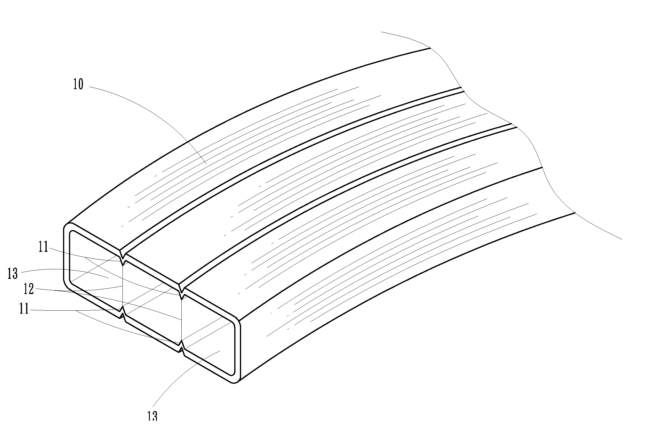
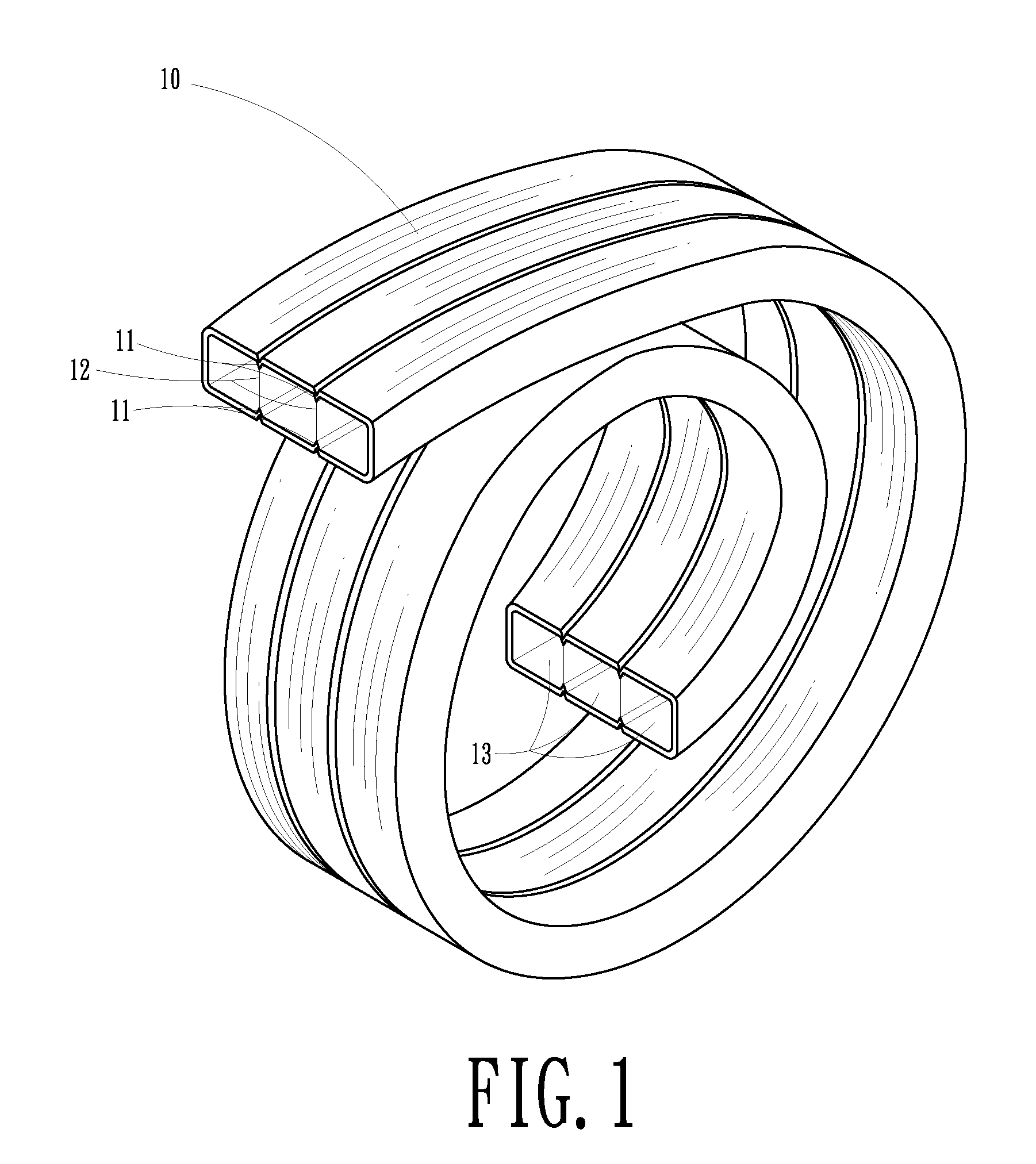
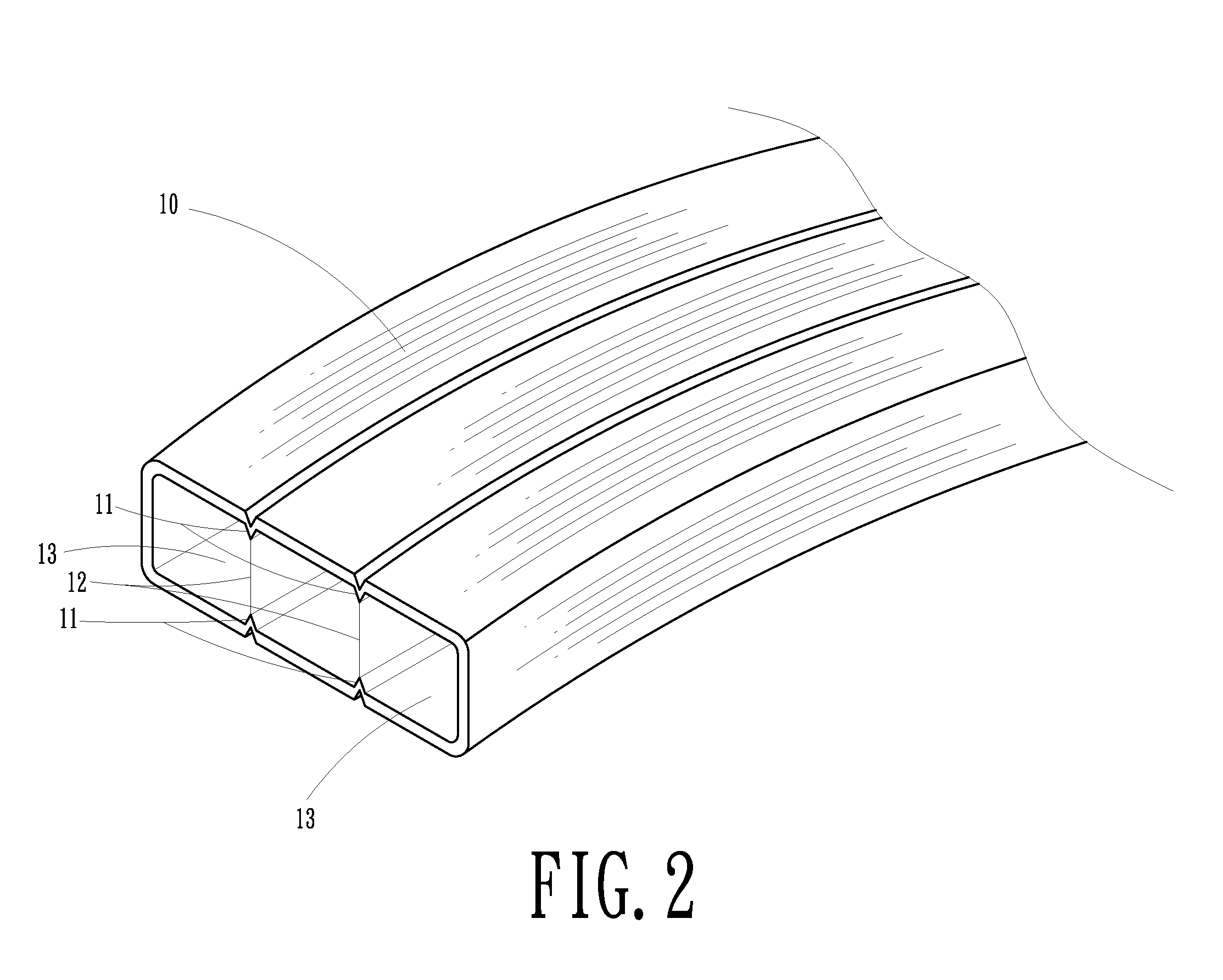
[0016]FIGS. 1 to 3 are perspective, partial, enlarged and front views schematically showing a flat pipe of the present invention.

[0017]The pipe comprises:

[0018]a main body 10 shaped as a tube or flat tube wherein opposite pairs of ridges 11 are installed at the inner upper and lower positions of the main body 10, and thin-film spacers 12 installed between said pairs of ridges 11. The placement of the thin-film spacers 12, which are flexible and formed of a thin film, form multiple passages 13 in the main body 10.

[0019]In light of the structures described above, the pres...


PUM


Abstract

A flat pipe with variable flow capacity comprises a main body shaped as a flat tube wherein opposing ridges are installed at the inner upper and lower positions of the main body, and thin-film spacers are installed between said pairs of ridges, forming multiple passages in the main body. Due to the flexibility of the thin-film spacers, the passages of the main body may stretch to a larger diameter to adjust to increased flow. If the flow is significantly enlarged, the main body will flex at the ridges causing the thin-film spacers to separate which in turn opens flow to the main body, essentially creating one main passage with a large diameter. When flow is stopped or decreased, the main body will restore elastically and resume shape as a flat pipe. According to the above, the present invention discloses a pipe which is easily stored and prevents twisting which could result in deformation, breakage and flow interference.

Description

BACKGROUND OF THE INVENTION[0001]1. Field of the Invention[0002]The present invention relates to a flat pipe. More particularly, the present invention relates to a pipe which allows the varied pressure of air or liquid to flow through.[0003]2. Description of Related Art[0004]A conventional pipe, as shown in FIG. 5 and FIG. 6, is usually shaped as a flat pipe 20 or a simple circular pipe 30, wherein the flat pipe 20 comprises spacers 21 used to prevent the pipe from twisting that may result in deformation and breakage of the pipe, further interfering with flow. In addition, the design of the spacers 21 also provides an easy means of rolling the pipe for storage purposes. However, the design of the spacers 21 limits the flow capacity of the flat pipe 20 such that only a small volume of flow is capable of running through the passages 22, resulting in inconvenience to the user.[0005]Regarding a circular pipe 30, although the diameter of the pipe is larger than that of a flat pipe and al...

Claims


Application Information

Patent Timeline
Patent Type & Authority Patents(United States)
IPC IPC(8): F16L11/00
CPCF16L9/003F16L11/121F16L9/19F16L9/006
Inventor WU, SHIH MING
Owner B H SHOW
Why Eureka
Try Eureka