Filler pipe arranging structure for vehicle

a technology of arranging structure and filler pipe, which is applied in the direction of transportation and packaging, transportation items, tank vehicles, etc., can solve the problems of undesired deformation of filler hoses and damage to the intermediate portion 107 of the hoses

Inactive Publication Date: 2008-09-09
HONDA MOTOR CO LTD
View PDF11 Cites 25 Cited by
  • Summary
  • Abstract
  • Description
  • Claims
  • Application Information

AI Technical Summary

Benefits of technology

[0005]An object of the present invention is to provide a filler pipe arranging structure which is capable of stably holding a filler pipe without deformation or damage even when the vehicle body frame is subjected to an impact force at a rear part thereof.
[0007]By virtue of the cross member extending crosswise between the rear side frames, the front portions of the rear side frames have a rigidity sufficient to withstand severe impact forces such as ones experienced in a rear-end collision. Since the filler pipe is attached to one of such rigid front portions of the rear side frames, the filler pipe arranging structure can keep the filler pipe free from deformation even when rear ends of the rear side frames undergo an impact force. The cross member disposed rearward of the fuel tank acts to protect the fuel tank from the impact force.
[0008]The filler pipe arranging structure vehicle may further have a rear suspension spring and a rear suspension damper disposed rearward of the rear axle, and the filler pipe is spaced forward from the rear suspension damper and the rear suspension spring. With this arrangement, there is provided on the forward side of the rear axle a relatively large space available for installation of the filler pipe. By the large installation space thus provided, the degree of freedom in designing the filler pipe can be increased. Thus, the filler pipe can take such a simple form as to insure smooth flow of fuel from the fueling port to the fuel tank.
[0011]It is preferable that the attachment portion of the filler pipe is located forwardly of the rear axle, and the rear cross member is disposed rearward of the rear axle. The rear cross member disposed rearward of the rear axle prevents transmission of an impact force from the rear ends of the rear side frames to the rear axle. Further, with the rear cross member disposed rearward of the rear axle, the space provided forwardly of the rear cross member for installation of the fuel tank is enlarged, and the capacity of the fuel tank can be increased correspondingly.
[0013]It is preferable that the front portions of the rear side frames have rigidity sufficient to withstand an impact force applied to rear ends of the rear side frames, and the rear side frames have rear portions located rearward of the rear cross member and deformable to absorb the impact force. When the rear ends of the rear side frames undergo an impact force, the rigid front portions do not deform while the rear portions deform to absorb the impact force. At this time, the filler pipe attached to the rigid front portion is kept free from deformation. The filler pipe can thus be kept in a normal deformation-free state at all times, which will insure smooth flow of fuel from the fueling port to the fuel tank.

Problems solved by technology

The disclosed filler pipe arranging structure has a drawback, however, that since the filler hose 102 is not fixed except at both ends thereof, an intermediate portion 107 of the hose may be damaged due to repeated striking engagement with neighboring vehicle parts or components occurring when the vehicle is traveling on a bumpy road or making sharp turns.
With this arrangement, when the vehicle body frame is subjected to a collision at a rear end thereof, the filler hose may undesirably deform due to the effect of an impact force applied thereto during deformation or buckling of the impact-absorbing portion of the vehicle body frame.

Method used


Image

  • Filler pipe arranging structure for vehicle
  • Filler pipe arranging structure for vehicle
  • Filler pipe arranging structure for vehicle

Examples


Embodiment Construction

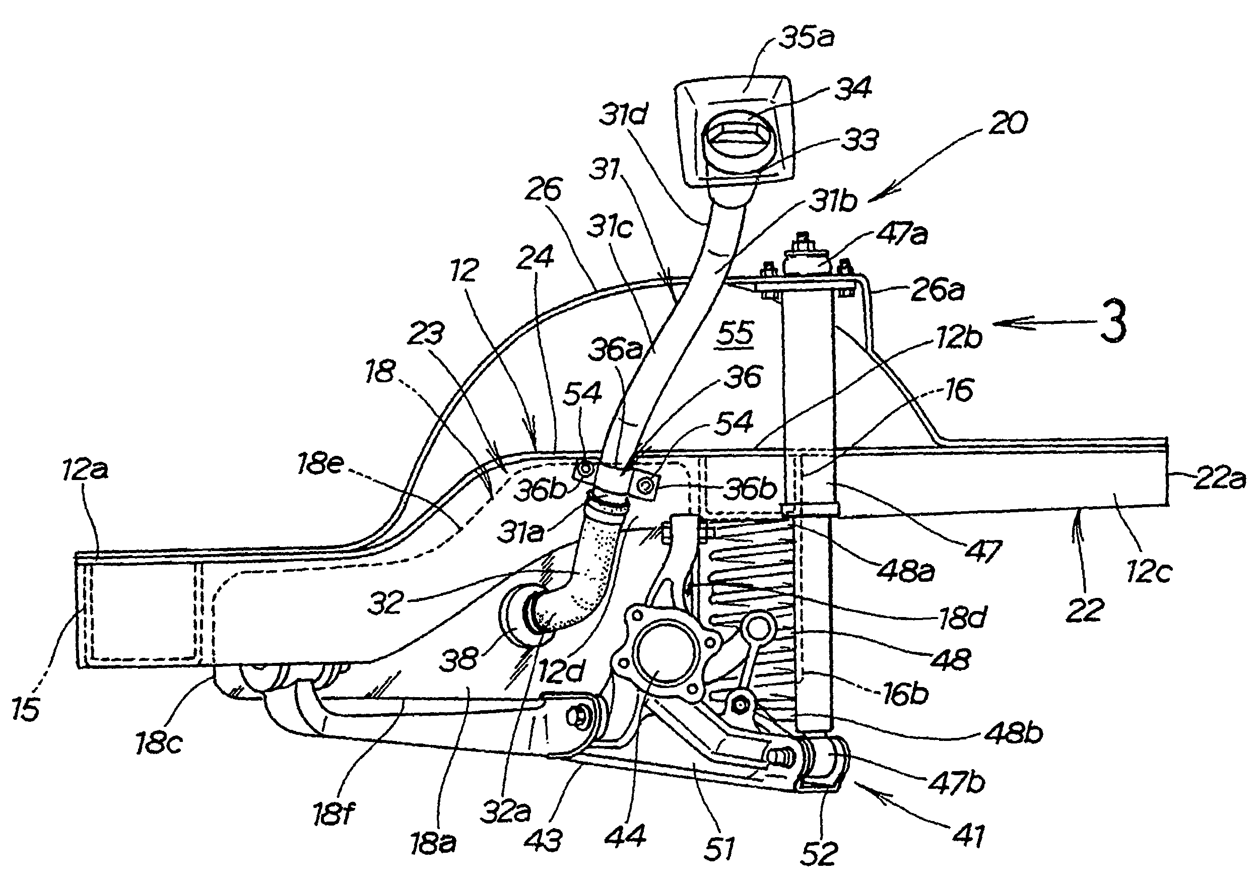
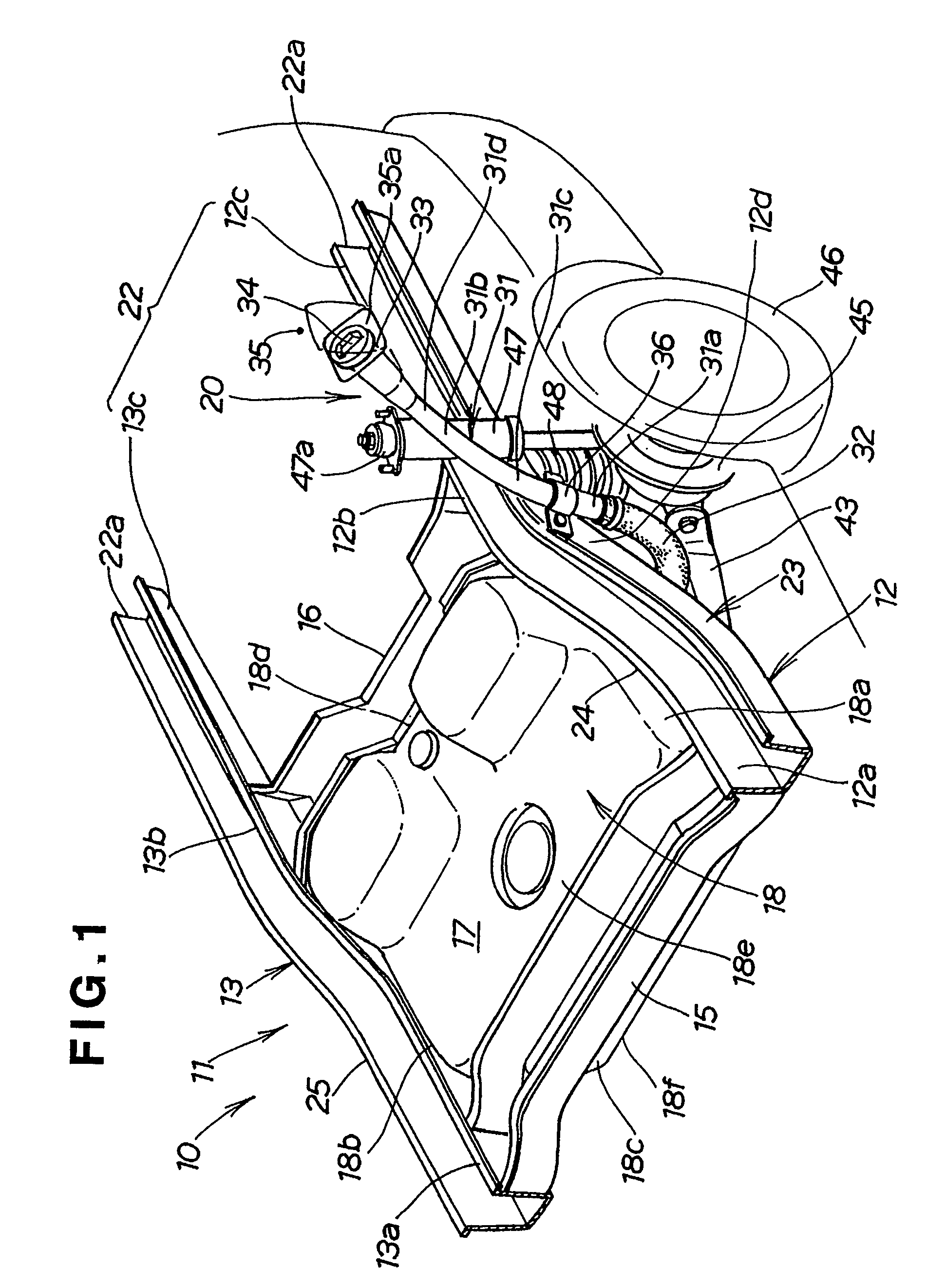
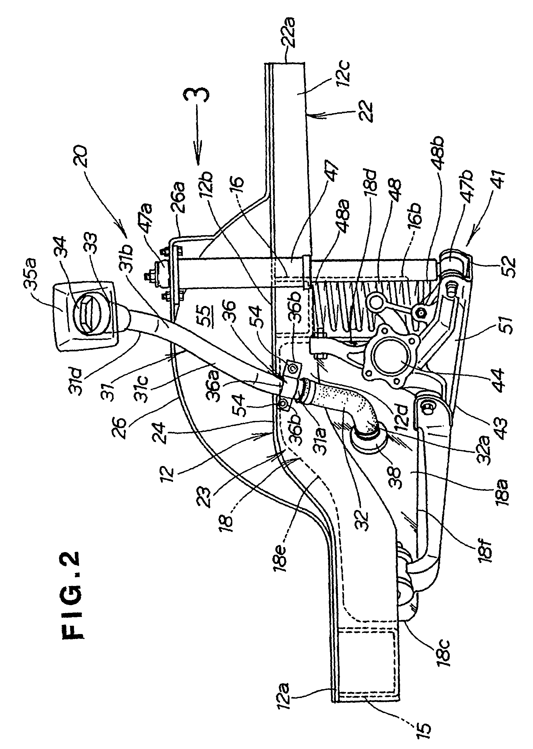
[0021]Referring to FIG. 1, a vehicle 10 includes a vehicle body frame 11 composed of left and right rear side frames 12, 13 extending in a longitudinal direction of a vehicle body (not designated) of the vehicle 10, a front cross member 15 extending crosswise between front ends 12a, 13a of the left and right rear side frames 12, 13 for reinforcing the rear side frames 12, 13, and a rear cross member 16 extending crosswise between substantially central portions 12b, 13b of the left and right rear side frames 12, 13 for reinforcing the left and right rear side frames 12, 13. The left and right rear side frames 12, 13 and the front and rear cross members 15, 16 jointly define a space 17 of substantially rectangular shape as viewed in top plan. The vehicle 10 also includes a fuel tank 18 received in the rectangular space 17.

[0022]By virtue of the rear cross member 16 extending crosswise between the left and right rear side frames 12, 13, the vehicle body frame 11 is formed with a rear p...


PUM


Abstract

A filler pipe arrangement structure (20) includes left and right rear side frames (12, 13) extending longitudinally of a vehicle body, and a rear cross member (16) disposed in the vicinity of rear axles and extending crosswise between the rear side frames so as to reinforce the rear side frames. A filler pipe (31) connected at an upper end to a fueling port (33) of the vehicle body and having a lower end connected via a filler hose (32) to a fuel tank (18) is attached to a left front portion (24) of the left rear side frame located forwardly of the rear cross member.

Description

TECHNICAL FIELD[0001]The present invention relates to a filler pipe arranging structure for arranging a filler pipe provided to guide a fuel from a fueling port of a vehicle into a fuel tank.BACKGROUND ART[0002]A filler pipe or hose connected to a fuel tank disposed below a vehicle floor for guiding a fuel to the fuel tank is known as disclosed in, for example, Japanese Utility Model Post-Exam Publication No. SHO-60-12746. The disclosed filler hose 102, as shown here in FIG. 5, has a lower portion 103 inserted in and connected to a fuel tank 101. A fueling port 104 is connected to an upper end of the filler hose 102 and mounted on a left side 106 of a vehicle body near a left rear wheel house 105. The filler hose 102 is arranged such that the lower portion 103 and an intermediate portion 107 extending upward from the lower portion 103 toward the fueling port 104 are disposed forwardly of a rear axle 108.[0003]With this arrangement, when an impact force is applied to a rear end of th...

Claims


Application Information

Patent Timeline
Patent Type & Authority Patents(United States)
IPC IPC(8): B60P3/22B60K15/04B62D25/20
CPCB60K15/04B60K2015/0474B60K15/01B62D21/15
Inventor MATSUMOTO, HIDEKIKANEKO, NAOMASAINOUE, HIROTO
Owner HONDA MOTOR CO LTD
Why Eureka
Try Eureka