Electronic device

a technology of electronic devices and slots, applied in the direction of typewriters, electric apparatus casings/cabinets/drawers, instruments, etc., can solve the problem that users might not be able to easily recognize the position, and achieve the effect of reducing the thickness of electronic devices, facilitating the insertion and removal of memory media into and from openings, and confirming the position of slot units

Inactive Publication Date: 2008-09-16
BROTHER KOGYO KK
View PDF7 Cites 35 Cited by
  • Summary
  • Abstract
  • Description
  • Claims
  • Application Information

AI Technical Summary

Benefits of technology

[0010]In this electronic device, the memory medium (typically, a compact memory card) can be mounted to the slot unit. Then, image data stored in the memory medium is read out. A user of the electronic device holds the memory medium, inserts the memory medium into the opening of the panel of the slot unit, and places the memory medium in the memory medium accommodating portion. Generally, the electronic device is placed on a desk, and the user operates the electronic device while standing or sitting in front thereof in many cases. Therefore, since the user usually operates the electronic device while looking downward, the user might not be able to recognize easily the position of the opening of the panel of the slot or the type of the compact memory card which can fit the slot. However, according to one embodiment of the invention, since the slot unit includes the panel having the swelled surface, the position of the slot unit can be recognized by the user immediately at a glance. In addition, since the mark is provided at a position of the swelled surface corresponding to the upper side of the opening, the position of the opening to which the memory medium is inserted and the type of the memory medium which can fit the opening can be recognized by the user immediately at a glance.
[0011]Preferably, the swelled surface is configured with a curved surface swelled toward the front side of the electronic device. Since the swelled surface is formed into the curved surface, when the user makes an attempt to insert the memory medium into the opening while groping for the opening with his / her hand, the user can easily find the position of the opening simply by sliding the memory medium along the surface of the panel.
[0013]Preferably, the guiding surface is configured with the curved surface depressed inwardly toward opening. Accordingly, the memory medium can be guided to the opening quite smoothly by bringing the memory medium held by the user into abutment with the guiding surface.
[0014]Preferably, a lower edge portion of the opening is projected toward the front side of the electronic device with respect to an upper edge portion of the opening so as to form a placing surface on which the memory medium can be placed at least when being inserted. In this configuration, when the user inserts the memory medium into the opening, the user can place the memory medium on the placing surface and insert the same into the opening. Accordingly, there is an advantage that the operation to insert the memory medium into the opening is more facilitated for the user. This advantage is obvious in particular when the user inserts the memory medium into the opening while groping for the opening with his / her hand, as described above.
[0017]The memory medium is formed into a sheet-shape or a thin plate shape in many cases. In this configuration, the memory medium is inserted horizontally from the front inwardly toward the image scanning unit. In addition, the slot unit is provided between the operation panel and the output port of the recording medium. Therefore, the thickness of the electronic device can be reduced and the electronic device can be designed to a compact thin shape.
[0018]According to one embodiment of the invention, the user can easily confirm the position of the slot unit, the position of the opening provided on the slot unit, and the type of the memory medium to be inserted into the opening. Therefore, the insertion and removal operation of the memory medium into and from the opening is quite easy, and consequently, the usability of the electronic device is improved.

Problems solved by technology

Therefore, since the user usually operates the electronic device while looking downward, the user might not be able to recognize easily the position of the opening of the panel of the slot or the type of the compact memory card which can fit the slot.

Method used


Image

  • Electronic device
  • Electronic device
  • Electronic device

Examples


Embodiment Construction

[0029]Referring now to the drawings, the invention will be described in detail on the basis of one or more exemplary embodiments.

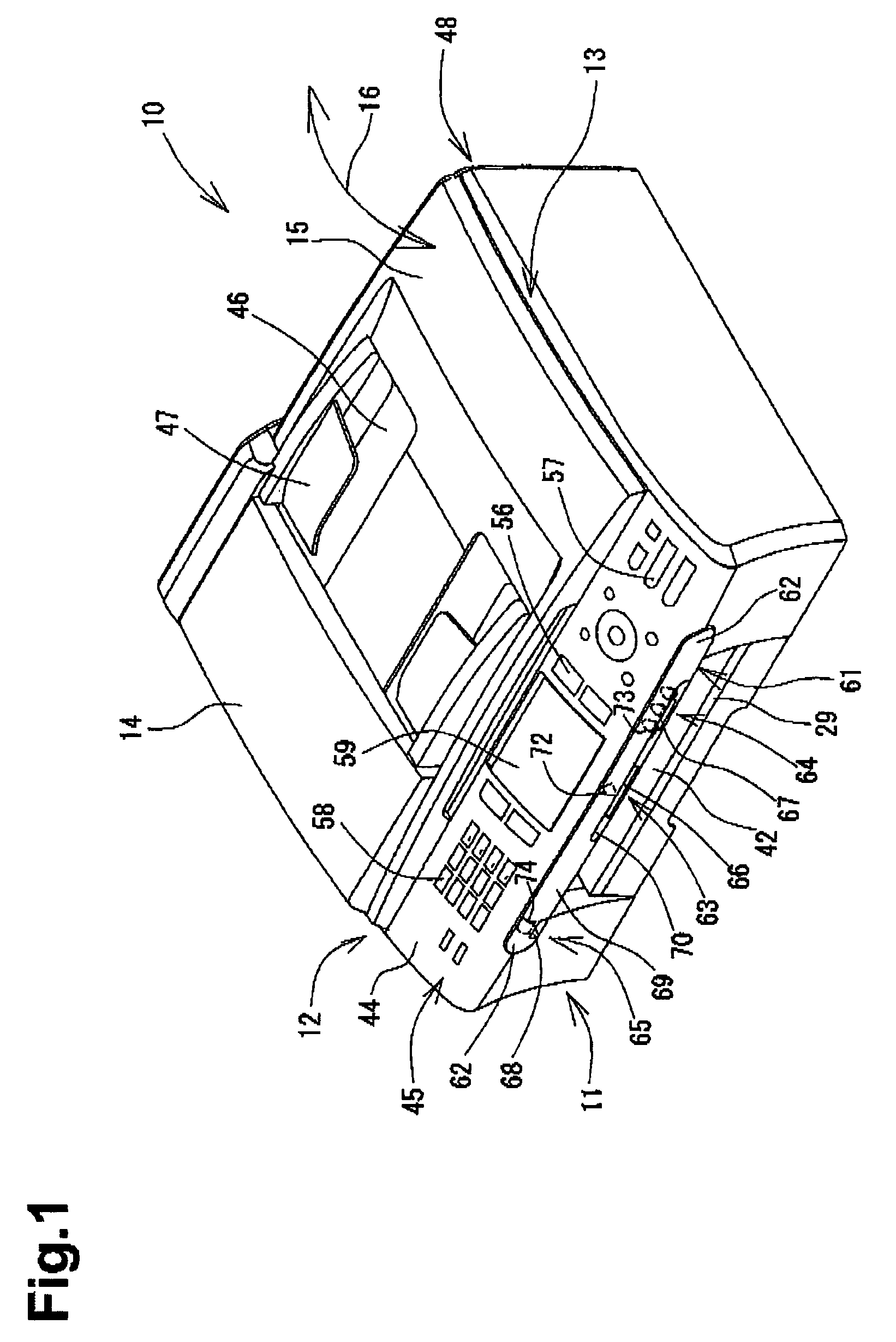
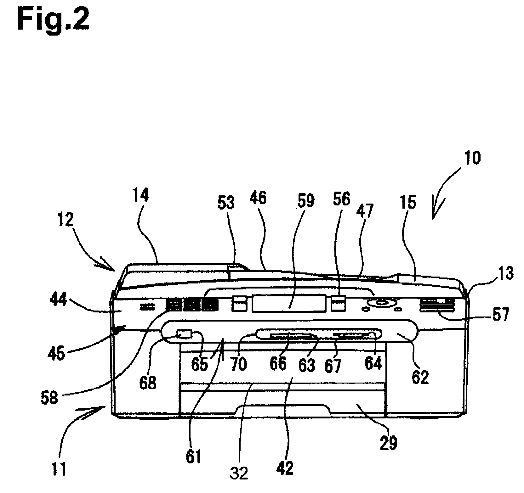
[0030]Referring to FIG. 1, a multi-function device 10 is provided integrally with a printer 11 (recording unit) on the lower side of the device 10, and a scanner 12 (image scanning unit) on the upper side of the device 10. The multi-function device 10 has a printing function, a scanning function, a copying function, and a facsimile function. The electronic device according to this embodiment of the invention is configured as the multi-function device 10. However, the electronic device according to another embodiment of the invention can be a device in which the printer 11 and the scanner 12 are not mounted. An example of this embodiment would include a card reader / writer which can read / record the image data with respect to a plurality of memory media.

[0031]The multi-function device 10 is usually connected to a computer (not shown) so as to record images or...


PUM


Abstract

An electronic device including a slot unit to which a memory medium is inserted. The electronic device is able to read out image data from the memory medium inserted to the slot unit. The slot unit includes a panel mounted to the front of the electronic device where the panel has a surface swelled toward the front side of the electronic device. The slot unit further includes a memory medium accommodating portion provided in the panel which on the swelled surface has an opening to which the memory medium is inserted. A mark representing the type of the memory medium to be inserted into the opening is provided at a position of the swelled surface corresponding to the upper side of the opening.

Description

[0001]The present invention is based on Japanese Patent Application No. 2005-261510 filed Sep. 9, 2005, the contents of which are incorporated by reference.BACKGROUND OF THE INVENTION[0002]1. Field of the Invention[0003]The present invention relates to a structure of an electronic device having a slot unit for mounting a memory medium at a front thereof.[0004]2. Discussion of Related Art[0005]In the related art, there is an electronic device which is provided with a slot unit for mounting a recording medium such as a compact memory card. The compact memory card can store image data or the like. When the compact memory card is connected to the slot unit, the electronic device can read the image data from the compact memory card. If the electronic device is provided with a recording unit which can record the image on a recording medium, such as a sheet of paper or the like, the image can be recorded on the basis of the read image data. The slot unit has an opening, for example, at the...

Claims


Application Information

Patent Timeline
Patent Type & Authority Patents(United States)
IPC IPC(8): H05K5/00
CPCB41J3/44H04N1/2158H04N1/00519H04N2201/0082
Inventor IKENO, TAKAHIROYAMAGUCHI, YASUTAKE
Owner BROTHER KOGYO KK
Why Eureka
Try Eureka