Current sensing apparatus

a current sensing and current technology, applied in the direction of measurement devices, instruments, measurement using dc-ac conversion, etc., can solve the problems of line loss associated with current flow, save shipping and mounting support costs, and achieve the effect of saving support costs

Inactive Publication Date: 2008-09-23
GENERAL ELECTRIC CO
View PDF6 Cites 11 Cited by
  • Summary
  • Abstract
  • Description
  • Claims
  • Application Information

AI Technical Summary

Benefits of technology

[0012]The current sensing apparatus of the present invention (also known as the Current sensor system or Cascade Sensor System (CSS)) is a lightweight alternative to a traditional current transformer (CT) that provide signals to low voltage devices such as meters and a wide range protection applications. As in all electrical systems there is line loss associated with current flow in electric lines. The Current Sensing Apparatus transmits a substantially accurate low level current signal from a first current transformer (mounted in, for example, mid-level 600V industrial switchgear frame) which steps the current down for travel over a long electric line of distance D; the step down minimizes line losses over the long line. The long electric line then connects to a smaller step-up unit, or second current transformer, mounted in proximity to a low voltage device such as an IED, meter or analog relay / protective device. The step-up unit provides, for example 5A electric signal to metering or protection applications; 5A is a traditional nominal rating for IEDs and the like in the United States. The 5A signal sees very little transmission line losses due to its proximity, over distance d, to the low voltage device, so a user does not need to specify burdens and relay class voltage when specifying the Current Sensing Apparatus for the application. The Current Sensing Apparatus is compatible with existing low voltage devices, such as IEDs, relays and meters. The Current Sensing Apparatus eliminates the need to perform numerous intricate, time-consuming calculations of the prior art to determine the power capacity including loss compensating calculations (i.e. excitation current and line loss) for a current transformer to perform in a specific installation.
[0013]Primary current, at utilization levels, is sensed by an induction current transformer or first current transformer with enough windings to yield a proportional secondary current signal much smaller than the traditional 5A nominal level that is typically specified for low voltage products, such as products powered by the 5A signal. This smaller signal is transmitted over lengthy electric lines much more efficiently than the traditional 5A signal. Further, the increased numbers of turns in the current sensing devices provide a sufficient voltage level. At a point just prior to a low voltage device such as a meter or relay point, the small signal is transformed by a second current transformer to a larger signal, typically a 5A signal to match the 5A input rating of the low voltage device. An important factor is that the small signal travels a comparatively short distance, d, with a comparatively smaller impedance and a comparatively smaller secondary winding resistance. This reduces the possibility of line loss and losses in the current transformer. Hence the apparatus of the present invention is used to obtain a small signal current for operating a low voltage device, where the small signal current is substantially proportional to a large primary current.
[0014]The CSS is lighter than traditional CTs. This will save shipping and mounting support costs. The CSS is smaller than traditional CTs. This will save mounting space that must be allocated to current sensing. It is easier to specify the CSS product than a traditional CT product because all CSS systems will meet 0.3% accuracy per IEEE C57.13 for metering, and will operate up to 20 times nominal rating for short bursts for relay over current sensing. Calculations and careful specification must be done with traditional products to insure this performance. In empirical testing, accuracy and voltage were measured to verify performance for metering and relaying. Preliminary results of empirical testing showed cost savings in the range of 11% to 36% and weight reduction in the range of 63% to 84%.
[0016]Due to the size and weight benefits, and not having to move away from the traditional 5 ampere basis, the alternative should look attractive to some customers. The simplification of specification and the opportunity of standardization will be attractive to some users.
[0021]This invention overcomes the disadvantages of the prior art by providing smaller, lighter, and less expensive current sensing apparatus CTs. The invention further overcomes the disadvantages of the prior art by providing self protection in that it is internally voltage limited for open circuit protection. The invention further overcomes the disadvantages of the prior art by operates over very long distances between sensors and connected devices without the need for tedious, time consuming, and sometimes inaccurate loss compensating calculations. The invention further overcomes the disadvantages of the prior art by providing energy savings. The invention further overcomes the disadvantages of the prior art because it is lightweight and dimensionally smaller and therefore physically able to fit in spaces unavailable for use with the prior art. The invention further overcomes the disadvantages of the prior art because more sensors can exist in the same space or the space allocated for the invention can be decreased. The invention further overcomes the disadvantages of the prior art because it can be shipped less expensively due to weight and physical size reductions.
[0022]The present invention does not require external control power. The present invention is easier to specify to a range of applications due to 0.3% accuracy. The invention does not need the inconvenience of fussing with relay class specification due to the range or protection to at least 20×. This reduces the need for a connection to a traditional power supply. The present invention does not require special re-education and training for users of prior art devices. The invention does not require change out of connected devices due to compatibility with existing devices such as relays and meters. The invention does not require support mechanisms used with traditional, heavier CTs, which is a cost savings.

Problems solved by technology

As in all electrical systems there is line loss associated with current flow in electric lines.
This will save shipping and mounting support costs.

Method used


Image

  • Current sensing apparatus
  • Current sensing apparatus
  • Current sensing apparatus

Examples


Embodiment Construction

[0036]In describing present invention, reference will be made herein to FIGS. 1-10 of the drawings in which like numerals refer to like features of the present invention. Referring now to the drawings, wherein like reference numerals designate identical or corresponding parts throughout the several views, one of the embodiments of the current sensing apparatus of the invention will be described. One of the advantageous aspects of an embodiment of the invention described here is a novel current sensing apparatus that smaller, lighter, and less expensive than previous current sensing apparatus while it is also accurate and conserves energy.

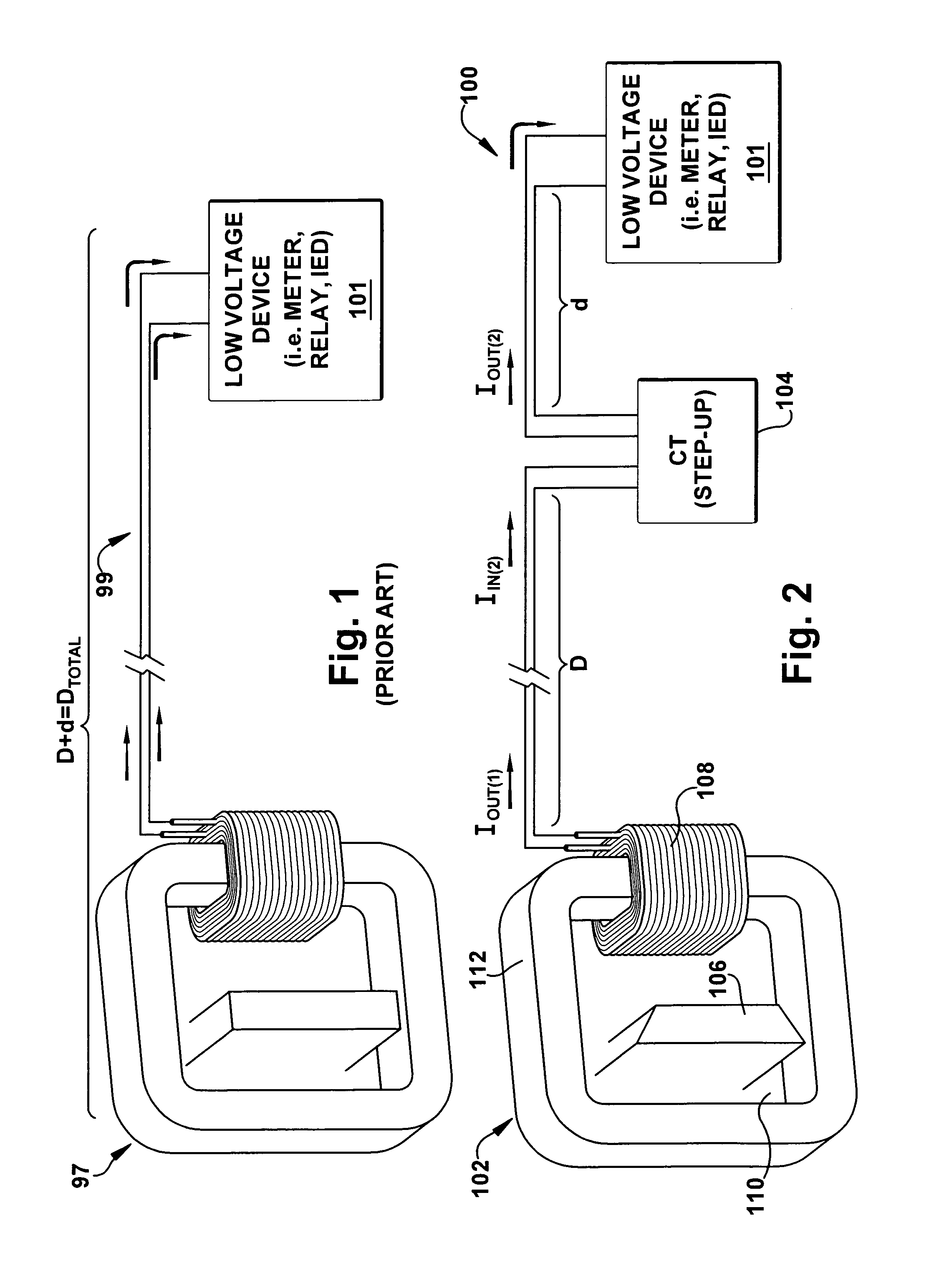
[0037]FIG. 2 illustrates a schematic block diagram of a current sensing apparatus 100 (also known as the current sensor system or Cascade Sensor System (CSS) of one embodiment of the present invention, supplying current to a device 101. The term “cascade” generally means “something arranged or occurring in a series or in a succession of stages so th...


PUM


Abstract

Disclosed is a current sensing apparatus which includes a first current transformer that, when energized, has a first input current and a first output current, the first output current being less than the first input current, the first current transformer stepping down the current. The current sensing apparatus includes a second current transformer in electrical communication with the first current transformer that, when energized, has a second input current and a second output current, where the second input current is substantially less than the first output current. The second output current being greater than the first output current, the second current transformer stepping up the current. The stepped up second output current is substantially equal to a nominally rated input current of a low voltage device in electrical communication with the second current transformer.

Description

BACKGROUND[0001]The present invention relates in general to current transformers and, more particularly, to current sensing devices for providing accurate current to meters and protection devices.[0002]Intelligent Electronic Devices (IEDs) are well known. IEDs include, for example, electronic trip units, protective relays, energy meters and power quality meters. By way of example, a protective relay typically is connected to the secondary side of one or more current sensors coupled to a power line. The current sensors provide analog signals indicative of the power line signals to the protective relay. In the case of IEDs, the analog signals are converted by an analog to digital (A / D) converter to digital signals which are processed by a microcontroller. Alternatively, where older equipment is in use, the analog signal is connected to an analog protective device, such as an electromechanical relay or analog meter. In either case, an analog signal of appropriate magnitude and reflecti...

Claims


Application Information

Patent Timeline
Patent Type & Authority Patents(United States)
IPC IPC(8): G01R15/18
CPCG01R15/185
Inventor JONES, KENT WARREN
Owner GENERAL ELECTRIC CO
Why Eureka
Try Eureka