[0012]The current sensing apparatus of the present invention (also known as the
Current sensor system or
Cascade Sensor System (CSS)) is a lightweight alternative to a traditional current transformer (CT) that provide signals to
low voltage devices such as meters and a wide range protection applications. As in all electrical systems there is
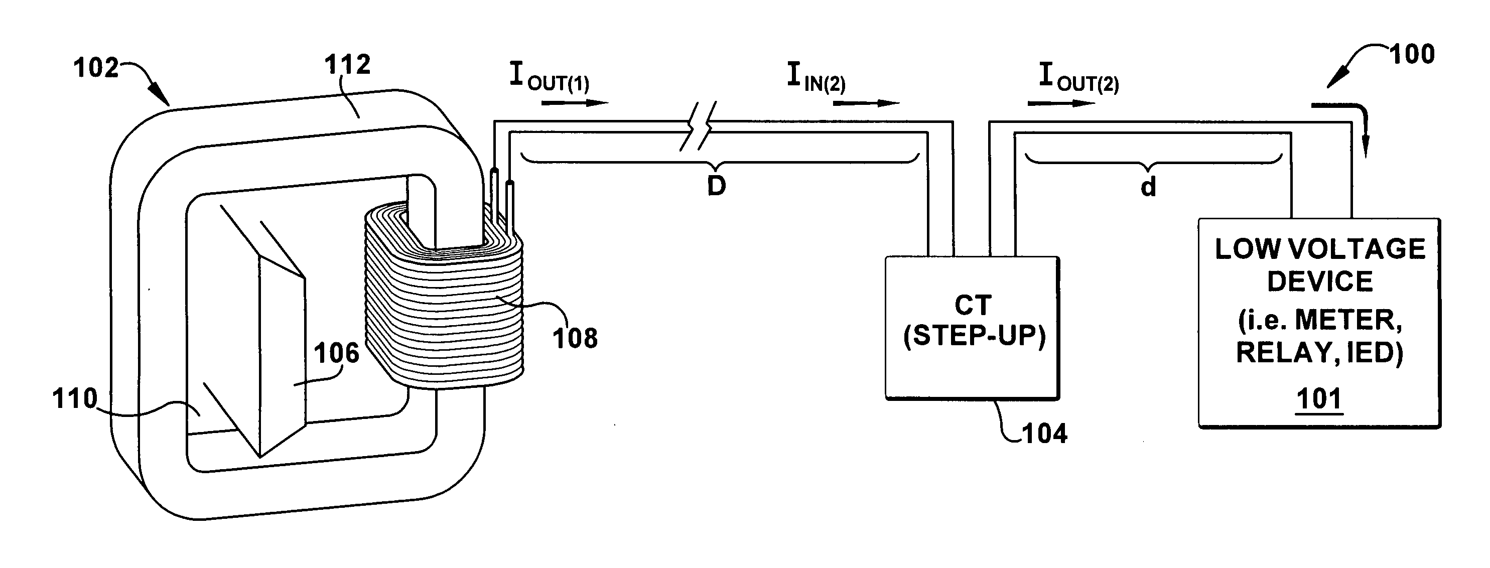
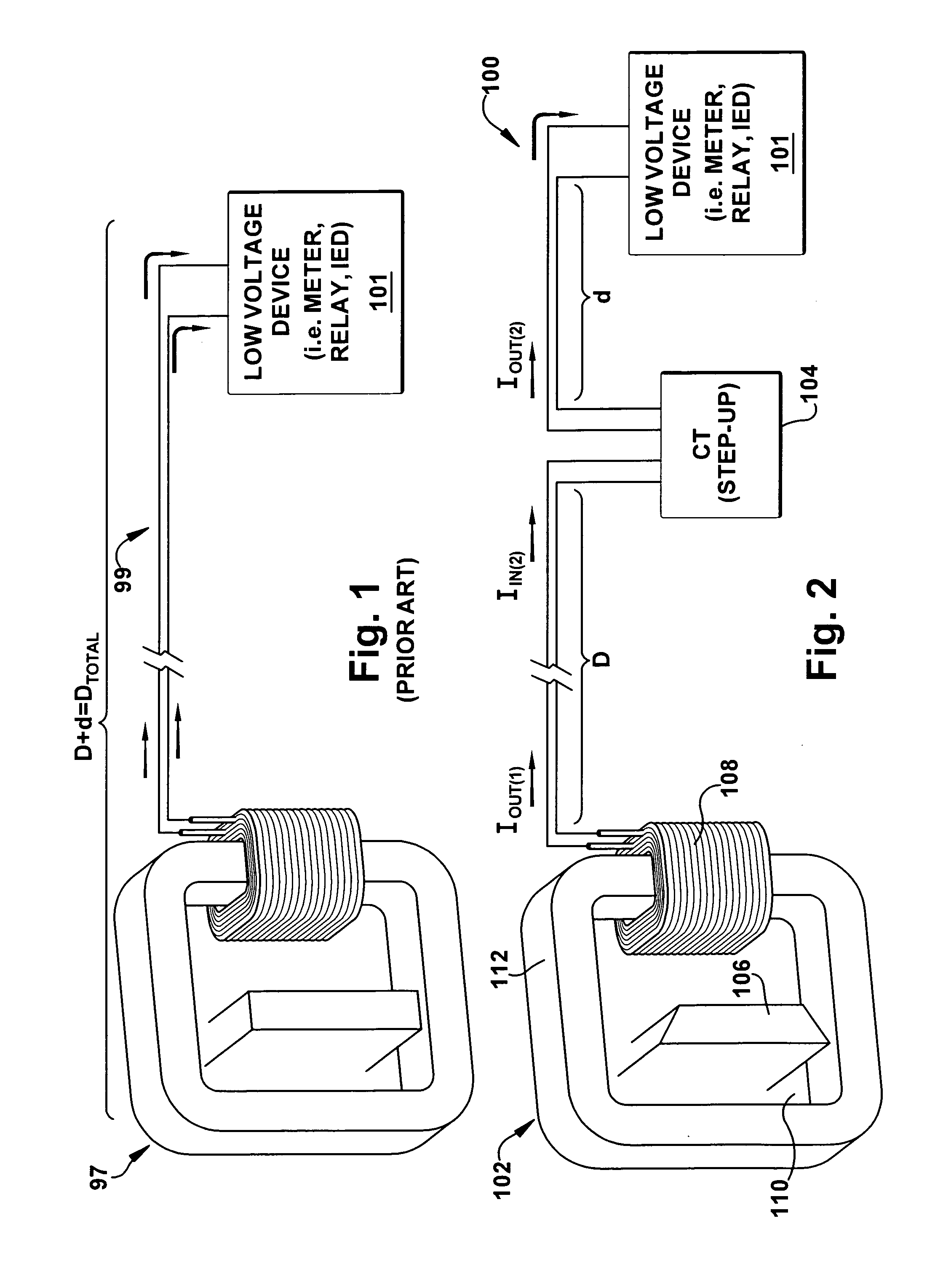
line loss associated with current flow in electric lines. The Current Sensing Apparatus transmits a substantially accurate low level current
signal from a first current transformer (mounted in, for example, mid-level 600V industrial
switchgear frame) which steps the current down for travel over a long electric line of distance D; the step down minimizes line losses over the long line. The long electric line then connects to a smaller step-up unit, or second current transformer, mounted in proximity to a
low voltage device such as an IED, meter or analog
relay / protective device. The step-up unit provides, for example 5 A
electric signal to metering or protection applications; 5 A is a traditional nominal rating for IEDs and the like in the United States. The 5 A
signal sees very little
transmission line losses due to its proximity, over distance d, to the low
voltage device, so a user does not need to specify burdens and
relay class
voltage when specifying the Current Sensing Apparatus for the application. The Current Sensing Apparatus is compatible with existing low
voltage devices, such as IEDs, relays and meters. The Current Sensing Apparatus eliminates the need to perform numerous intricate, time-consuming calculations of the prior art to determine the
power capacity including loss compensating calculations (i.e.
excitation current and
line loss) for a current transformer to perform in a specific installation.
[0013]Primary current, at utilization levels, is sensed by an induction current transformer or first current transformer with enough windings to yield a proportional secondary current
signal much smaller than the traditional 5 A
nominal level that is typically specified for low voltage products, such as products powered by the 5 A signal. This smaller signal is transmitted over lengthy electric lines much more efficiently than the traditional 5 A signal. Further, the increased numbers of turns in the current sensing devices provide a sufficient voltage level. At a point just prior to a low voltage device such as a meter or relay point, the small signal is transformed by a second current transformer to a larger signal, typically a 5 A signal to match the 5 A input rating of the low voltage device. An important factor is that the small signal travels a comparatively
short distance, d, with a comparatively smaller impedance and a comparatively smaller secondary winding resistance. This reduces the possibility of line loss and losses in the current transformer. Hence the apparatus of the present invention is used to obtain a small signal current for operating a low voltage device, where the small signal current is substantially proportional to a large primary current.
[0014]The CSS is lighter than traditional CTs. This will save shipping and mounting support costs. The CSS is smaller than traditional CTs. This will save mounting space that must be allocated to current sensing. It is easier to specify the CSS product than a traditional CT product because all CSS systems will meet 0.3% accuracy per IEEE C57.13 for metering, and will operate up to 20 times nominal rating for short bursts for relay over current sensing. Calculations and careful specification must be done with traditional products to insure this performance. In empirical testing, accuracy and voltage were measured to verify performance for metering and relaying. Preliminary results of empirical testing showed
cost savings in the range of 11% to 36% and weight reduction in the range of 63% to 84%.
[0016]Due to the size and weight benefits, and not having to move away from the traditional 5
ampere basis, the alternative should look attractive to some customers. The simplification of specification and the opportunity of
standardization will be attractive to some users.
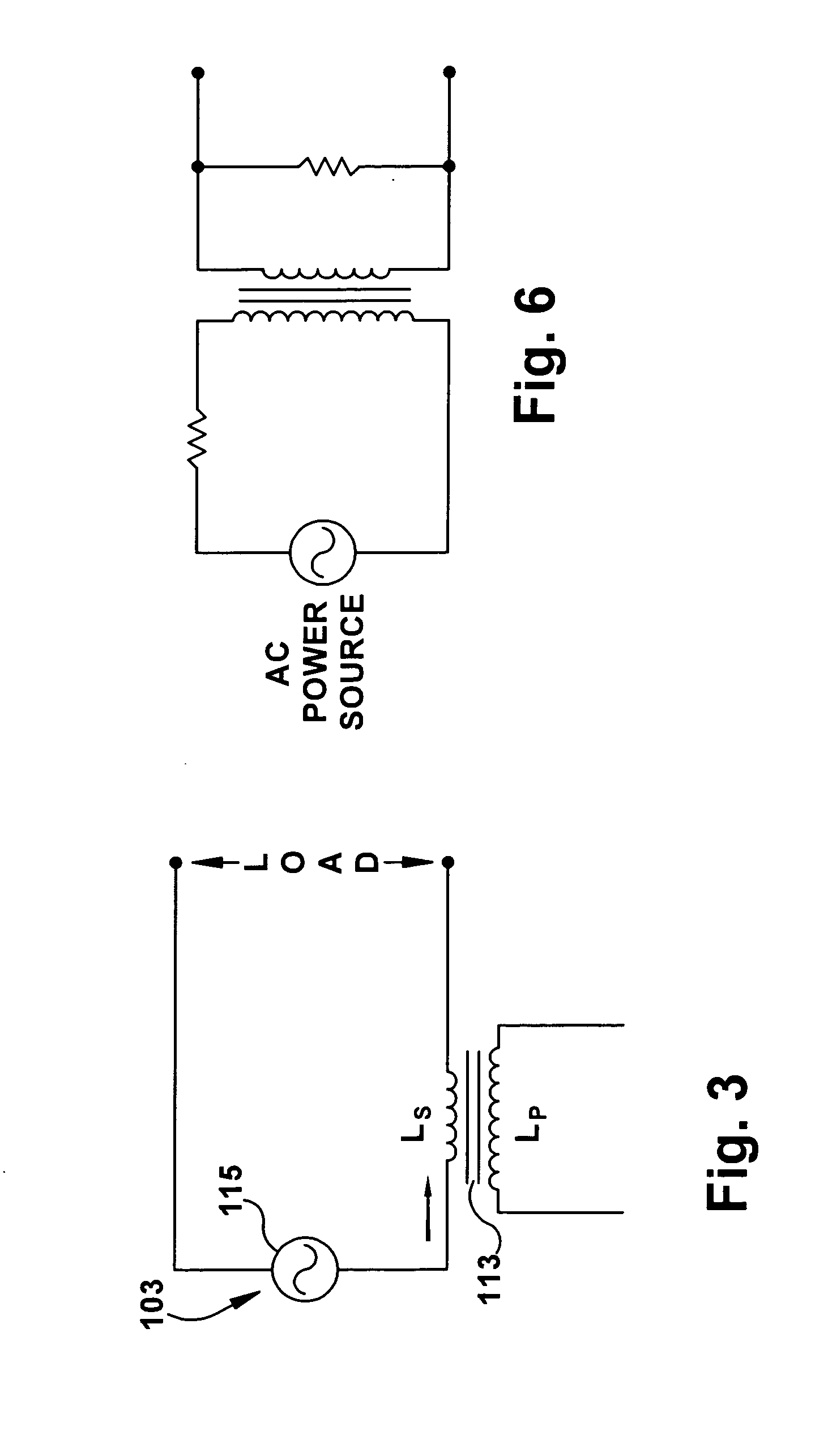
[0021]This invention overcomes the disadvantages of the prior art by providing smaller, lighter, and less expensive current sensing apparatus CTs. The invention further overcomes the disadvantages of the prior art by providing
self protection in that it is internally voltage limited for open
circuit protection. The invention further overcomes the disadvantages of the prior art by operates over very long distances between sensors and connected devices without the need for tedious,
time consuming, and sometimes inaccurate loss compensating calculations. The invention further overcomes the disadvantages of the prior art by providing energy savings. The invention further overcomes the disadvantages of the prior art because it is lightweight and dimensionally smaller and therefore physically able to fit in spaces unavailable for use with the prior art. The invention further overcomes the disadvantages of the prior art because more sensors can exist in the same space or the space allocated for the invention can be decreased. The invention further overcomes the disadvantages of the prior art because it can be shipped less expensively due to weight and physical size reductions.
[0022]The present invention does not require external
control power. The present invention is easier to specify to a range of applications due to 0.3% accuracy. The invention does not need the inconvenience of fussing with relay class specification due to the range or protection to at least 20×. This reduces the need for a connection to a traditional power supply. The present invention does not require special re-education and training for users of prior art devices. The invention does not require change out of connected devices due to compatibility with existing devices such as relays and meters. The invention does not require support mechanisms used with traditional, heavier CTs, which is a
cost savings.

