Three-dimensional light ray input apparatus

a technology of light ray input and three-dimensional image, which is applied in the direction of optics, lenses, instruments, etc., can solve the problems of complex processing of display, deterioration of 3d image quality, and problem of vareation among driving mechanisms, etc., and achieve the effect of being inexpensiv

Inactive Publication Date: 2008-10-07
KK TOSHIBA
View PDF6 Cites 35 Cited by
  • Summary
  • Abstract
  • Description
  • Claims
  • Application Information

AI Technical Summary

Benefits of technology

[0016]According to the present invention, an inexpensive and space-saving three-dimensional light ray input apparatus can be offered.

Problems solved by technology

If a large number of cameras are used, the 3D-image quality is deteriorated due to vareations among the individual cameras and installation accuracy.
Furthermore, where moving cameras are used, vareations among driving mechanisms present problems.
However, in the first prior-art technique, it is necessary to scan readjusting the angle of light rays.
Furthermore, it is required complex processing for displayed to an auto-stereoscopic display device using lenticular sheets or microlens arrays.
Additionally, parallel light images cannot be taken in vicinities of the object because there are not relay lenses.
This poses the problem that the equipment is increased in size.
Another problem is that the camera angle needs to be varied to obtain information.
One, it is limited that a range of light rays gained in one operation because a lens-array is used.
Tow, this leads to a deterioration of the resolution.
Three, the equipment is increased in cost and size.

Method used


Image

  • Three-dimensional light ray input apparatus
  • Three-dimensional light ray input apparatus
  • Three-dimensional light ray input apparatus

Examples


embodiment 1

(3) Modified Embodiment 1

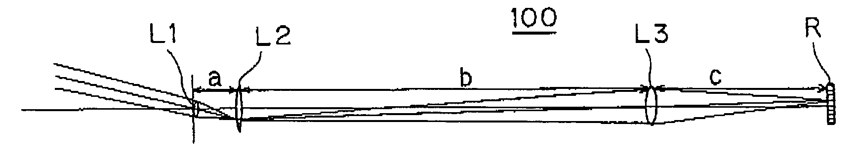
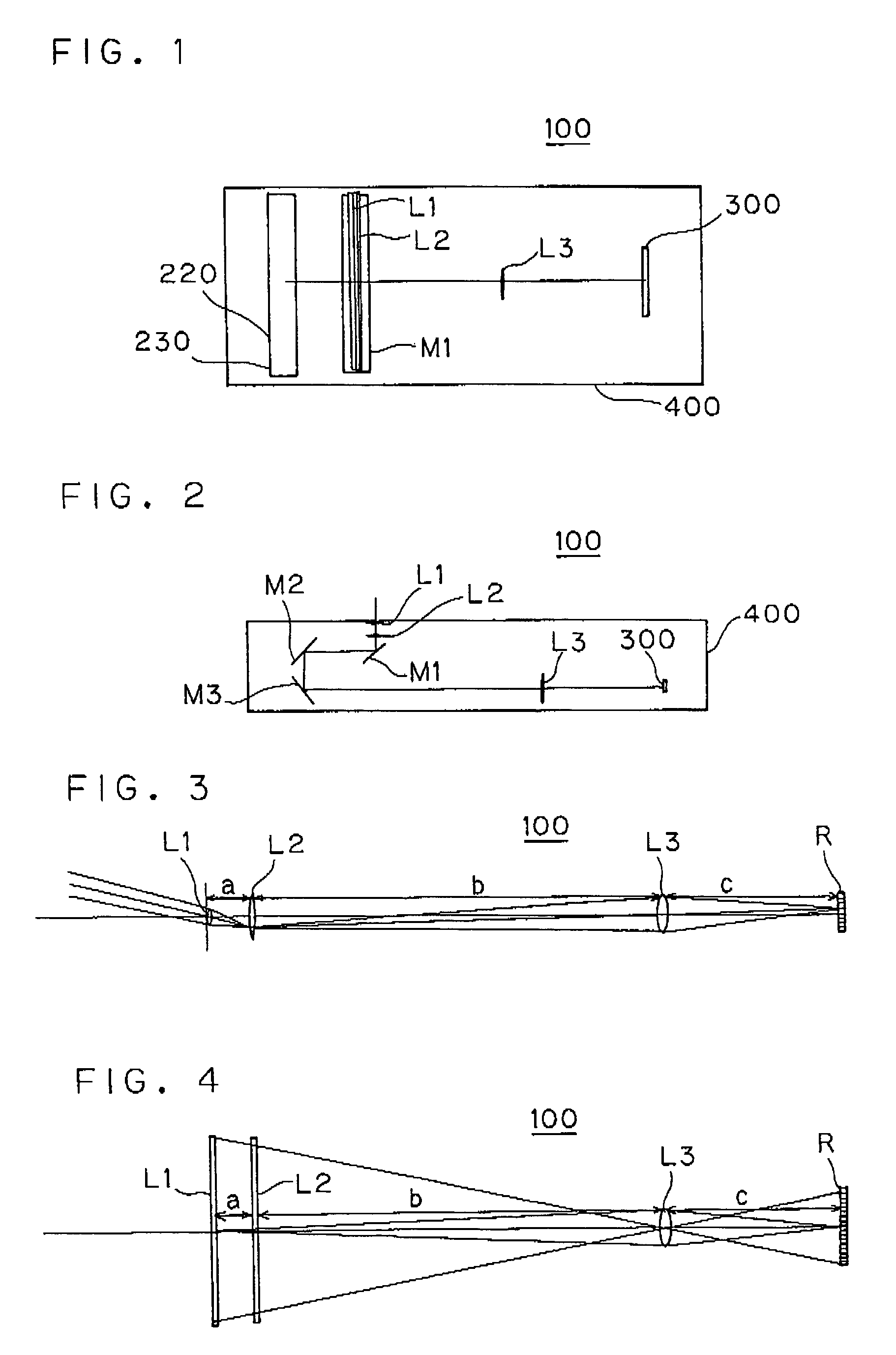
[0109]It is also conceivable to perform scanning via three mirrors in the same way as in Embodiment 1. Lens L2 and mirror M1 are disposed integrally. Mirrors M2 and M3 are moved at a half velocity of scanning M1 to enter light the focusing lens L3 such as same distance.

embodiment 2

(4) Modified Embodiment 2

[0110]It is also conceivable to control the shape of the aperture S incident on the L3 in the vertical direction and in the horizontal direction independently. The size of the aperture in the vertical direction corresponds to the image depth of field. The size of the aperture in the horizontal direction corresponds to the obtained resolution (resolution of the light rays) in the horizontal direction. If the aperture is made smaller, obtainable is better resolution of the light rays. However, the aperture is corresponded the amount of light (exposure) in use, the aperture is adjusted vertically and horizontally according to the circumstances.

embodiment 3

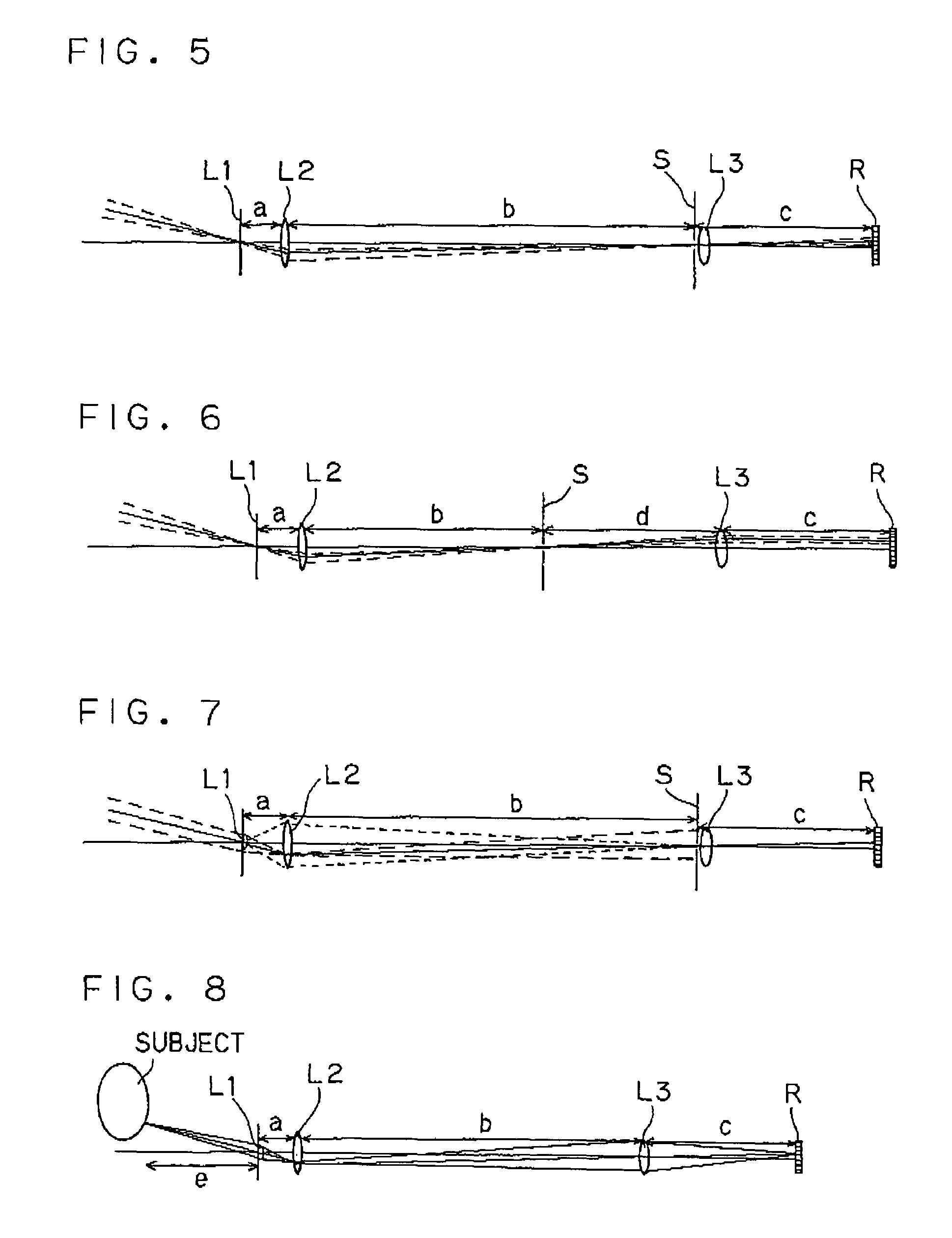
[0111]A three-dimensional light ray input apparatus 100 of Embodiment 3 is next described by referring to FIG. 6.

[0112]In the present embodiment, a slit S is placed into the position of the focal plane on the object side of the lens L3. Thus, the lens L3 selects parallel light focusing image sensor. This also yields advantages similar to those of Embodiment 2. In this case, image sensor area is more than wide lens L3 length in horizontal direction.


PUM


Abstract

A three-dimensional input apparatus includes a lens L1 for converting angular information about light rays from a object, a focusing element L3 for focusing the light rays from the object to the vicinities of an array R of photoelectric elements, and a lens L2 for performing conversion into a real image near the surface of the focusing element L3. The lens L2 is present between the lens L1 and focusing element L3. The array R records light as image signal sequentially. A driver portion drives the optical system and scans light ray information about the object.

Description

CROSS-REFERENCE TO RELATED APPLICATION[0001]This application is based upon and claims the benefit of priority from the prior Japanese Patent Application No. 2005-263096, filed on Sep. 9, 2005 and the prior Japanese Patent Application No. 2006-239587, filed on Sep. 4, 2006, the entire contents of which are incorporated herein by reference.TECHNICAL FIELD[0002]The present invention relates to a three-dimensional light ray input apparatus for obtaining light ray information displayed on a three-dimensional image reconstruction apparatus.BACKGROUND OF THE INVENTION[0003]There has been used multi-camera or moving camera as input system to obtain information about a three-dimensional (3D) image.[0004]If a large number of cameras are used, the 3D-image quality is deteriorated due to vareations among the individual cameras and installation accuracy. Furthermore, where moving cameras are used, vareations among driving mechanisms present problems.[0005]The following techniques have been propo...

Claims


Application Information

Patent Timeline
Patent Type & Authority Patents(United States)
IPC IPC(8): G02B26/08G02B30/27G02B30/30
CPCG02B27/2214G02B30/30G02B30/27
Inventor MOMONOI, YOSHIHARUTAIRA, KAZUKI
Owner KK TOSHIBA
Why Eureka
Try Eureka