

Image forming apparatus
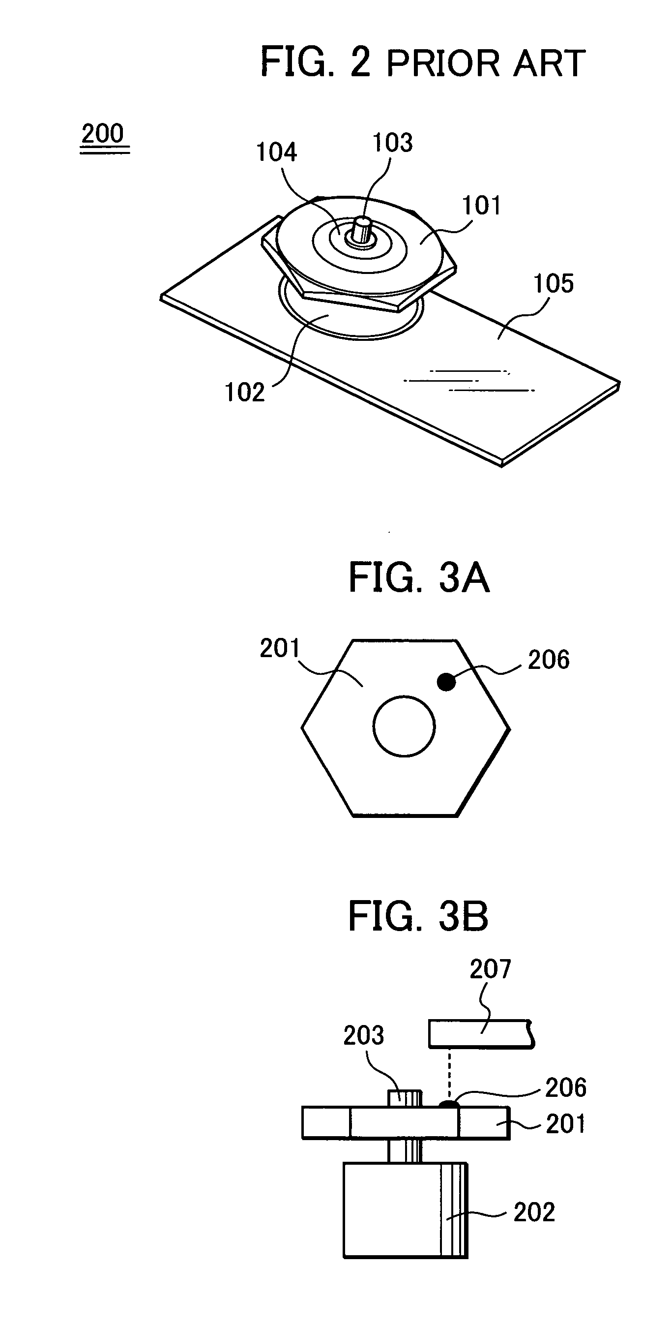
a technology of image forming apparatus and forming apparatus, which is applied in the direction of inking apparatus, electrographic process, instruments, etc., can solve the problems of motor assembly b>200/b> to have an imbalance problem, source of noise, etc., and achieves stable noise reduction effect and cost saving. cost
- Summary
- Abstract
- Description
- Claims
- Application Information
AI Technical Summary
Benefits of technology
Problems solved by technology
Method used
Image

Examples
first exemplary embodiment
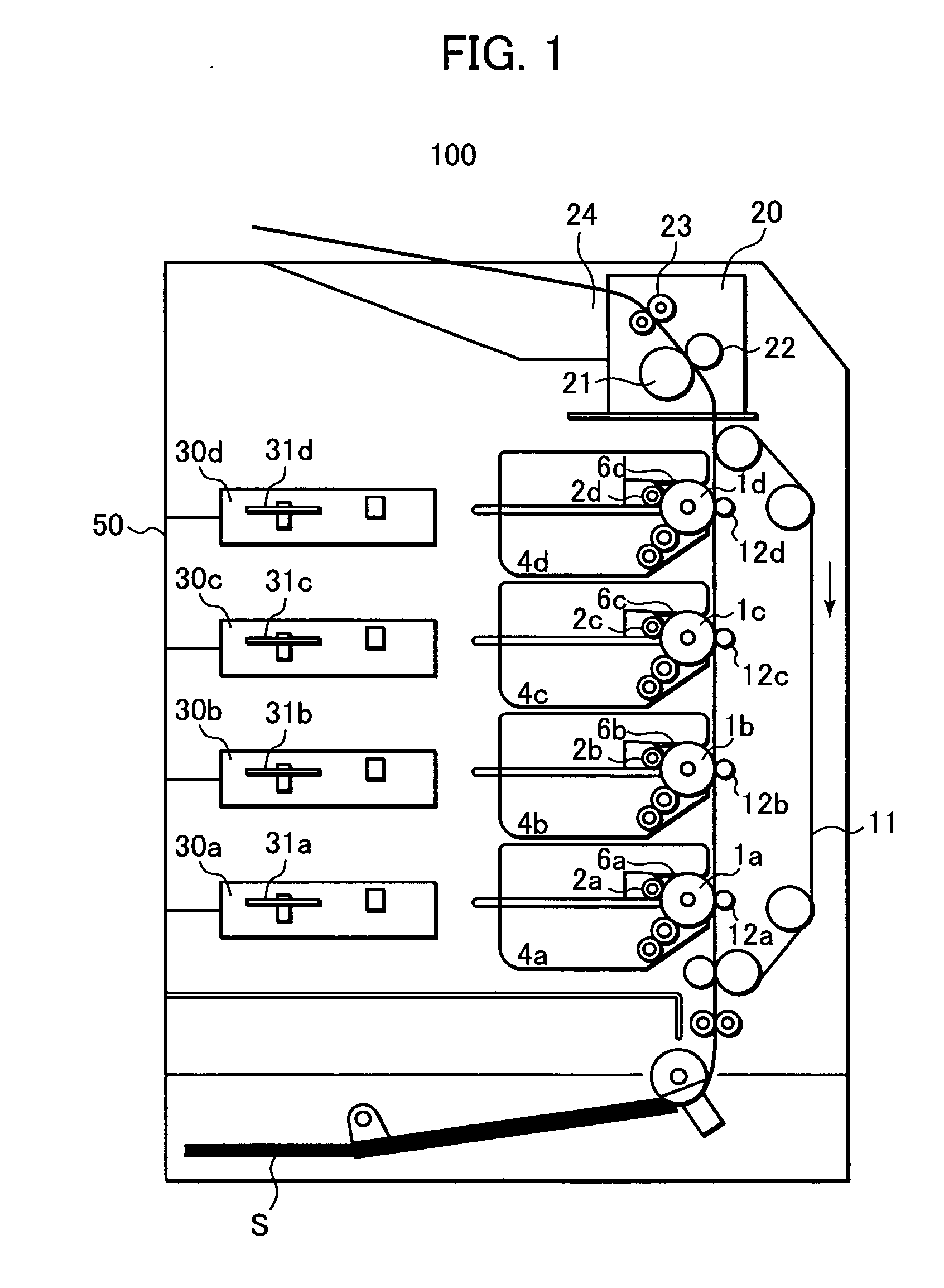
[0037]FIG. 1 is a sectional schematic view illustrating an essential configuration of an image forming apparatus in an exemplary embodiment of the present invention. The image forming apparatus 100 incorporates four electro-photographic conductor drums (which will be herein below referred to as “photoreceptor drums”) 1a, 1b, 1c, 1d for yellow, magenta, cyan and black, which serve as image bearing mediums and which are arranged linearly in a vertical direction in a parallel relation, and a conveyer belt 11 laid along the photoreceptor drums 1a to 1d, and serving as a transfer medium conveying unit for adsorbing thereto a recording sheet S as a transfer sheet which is adsorbed thereto through electrostatic adsorption.
[0038] Primary chargers 2a, 2b, 2c, 2d are arranged respectively around the photoreceptor drums 1a, 1b, 1c, 1d for uniformly charging the outer surfaces of the photoreceptor drums 1a to 1d, in the mentioned order from the upstream side in the rotating direction. Also, ex...
second exemplary embodiment
[0065]FIG. 9 is a sectional schematic view illustrating an exemplary configuration of the image forming apparatus in this embodiment. An image forming apparatus 101 has a similar configuration as that of the first embodiment shown in FIG. 1, except that a vibration detector system 51 serving as a vibration detecting unit is provided in the housing 50. It is noted that the detecting unit for a direction of weight imbalance and the phase control unit in the direction of weight imbalance are not provided in this embodiment.
[0066] Explanation will now be made of the relationship between the exposure units 30a to 30d and the housing 50 with reference to FIG. 10 which is a schematic plan view which shows the exposure units 30a to 30d which are supported at their left and right sides by a left side panel 52 and a right side panel 53 and at their rear sides by the housing 50.
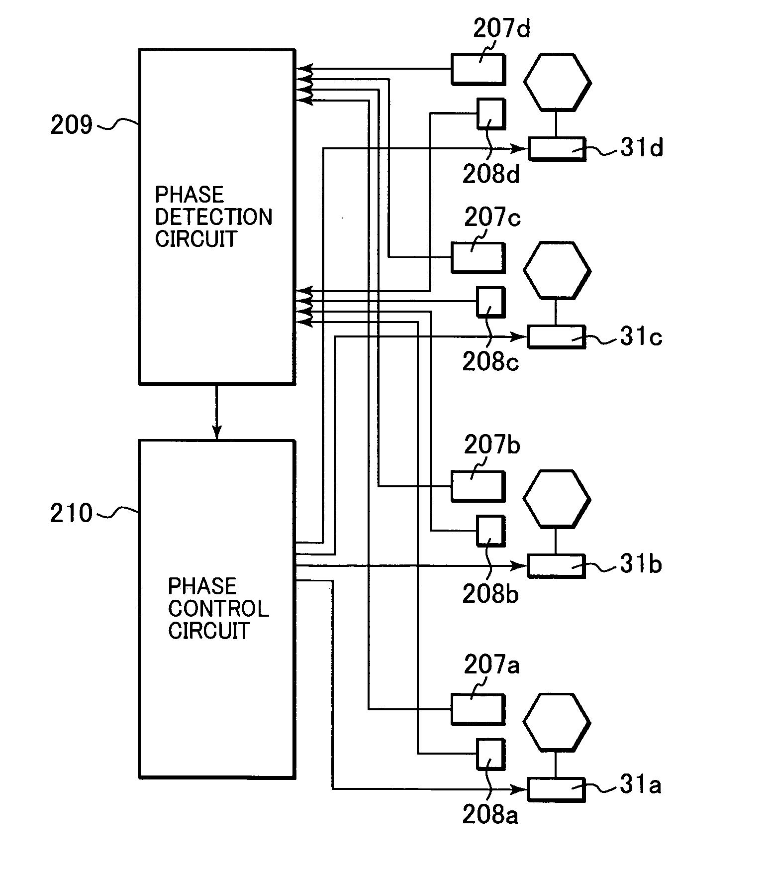
[0067] Further, the polygon motor motors 31a to 31d are located at positions as shown in FIG. 10. Thus, vibration o...
PUM
 Abstract
Description
Claims
Application Information