Image forming apparatus with noise reduction

a technology of image forming apparatus and noise reduction, which is applied in the direction of inking apparatus, electrographic process, instruments, etc., can solve the problems of motor assembly b>200/b> having an imbalance problem, noise source, etc., and achieves stable noise reduction effect and cost saving. cost

Inactive Publication Date: 2009-05-05
CANON KK
View PDF8 Cites 2 Cited by
  • Summary
  • Abstract
  • Description
  • Claims
  • Application Information

AI Technical Summary

Benefits of technology

[0015]The present invention is devised in view of the problems as stated above, and accordingly, one aspect of the present invention to provide an image forming apparatus which is inexpensive and space-saving and which may exhibit stable noise reduction effects, with no provision of vibration preventing members, acoustic members, sound suppressing members and the like.
[0021]Therefore, according to the embodiments of the present invention, by detecting a direction of weigh imbalance of the polygon mirror motor so as to control the phase to a specific phase with which the vibration of the polygon mirror motor is attenuated, and by providing the vibration detectors so as to fix the rotated phase of the polygon mirror motor with the timing with which the vibration of the housing is attenuated, in order to control the phase to a phase with which vibration of the housing is attenuated, stable noise reduction with low costs and with space saving may be made with no provision of vibration preventing members, acoustic members, sound suppressing members or the like.
[0022]Accordingly, there may be provided an image forming apparatus which is inexpensive and space saving, and which can exhibit an effect of noise reduction, with no addition of vibration preventing members, acoustic members and sound suppressing members.

Problems solved by technology

These components cause vibration which is a source of noise.
Further, this vibration also vibrates other components, resulting in more noise within the image forming apparatus.
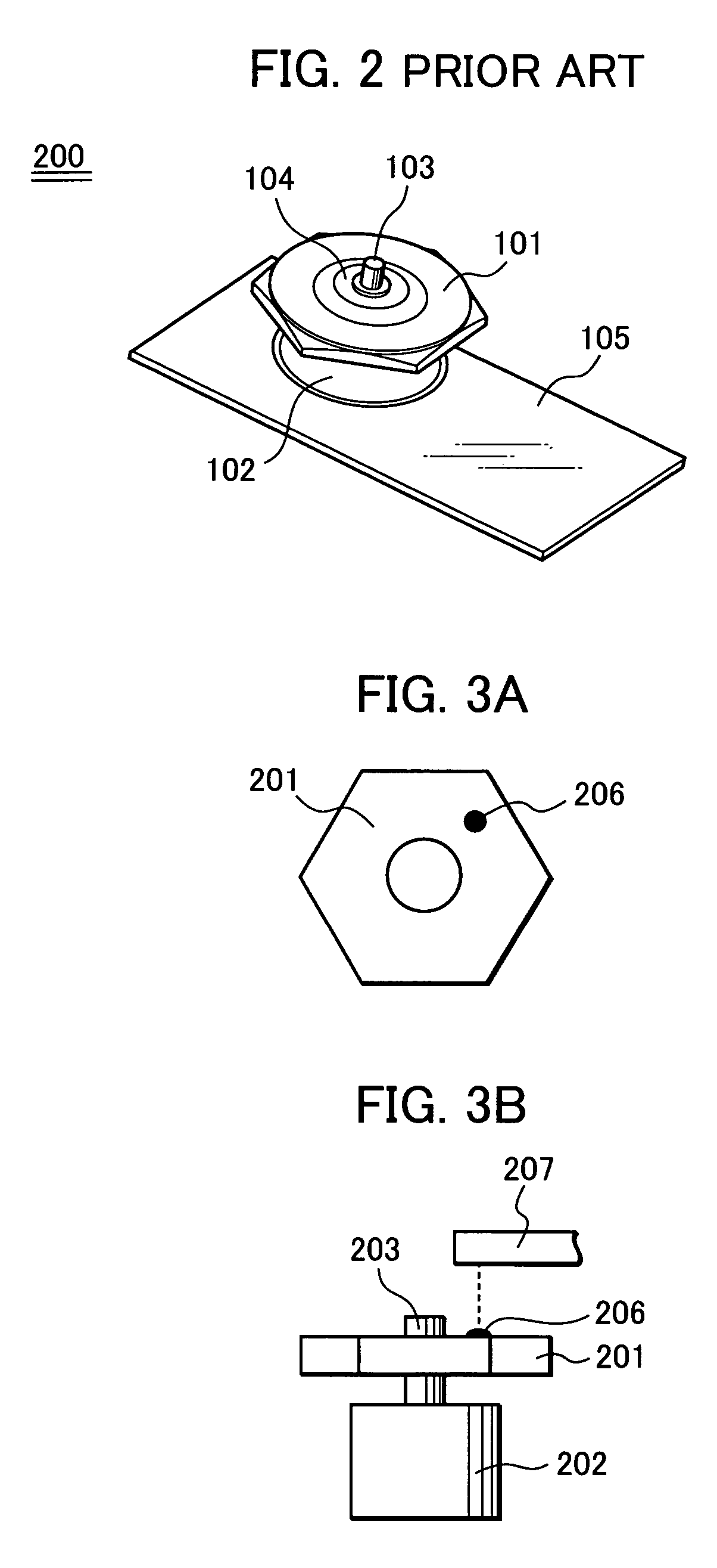
However, the aforementioned gaps are disadvantageous because they cause the polygon mirror motor assembly 200 to have an imbalance problem.
That is, the rotary polygon mirror 101 fitted on the rotary shaft 103 is movable more or less in a radial direction due to these gaps, resulting in weight imbalance.
However, in view of the weight of the imbalance correction putty, the degree of accuracy of the coating, and the like, the aforementioned remedial attempt to achieve an adequate balance is still typically insufficient to improve the weight imbalance.
Further, in order to ensure a nominal yield, it is necessary to tolerate or accept polygon mirrors 101 which have an inherent imbalance problem.
Therefore, a typical image forming apparatus having a plurality of optical scanning units, each including a polygon mirror having the above-mentioned configuration, has several problems associated with it.
Another problem pertains to the vibration from the optical scanning units, caused by weight imbalance of the polygon mirror motors 102 which is transmitted to a housing serving as a structure for supporting the rear surfaces of the optical scanning units, resulting in generation of noise.
As a result, the noise is also changed each time when the image forming apparatus is energized.
However, in the above-mentioned conventional example, acoustic members, sound suppressing members and the like are added in the apparatus, and as a result, the volume of the apparatus is increased, and the amount of work during assembly of the image forming apparatus is also increased so as to increase the costs of production.

Method used


Image

  • Image forming apparatus with noise reduction
  • Image forming apparatus with noise reduction
  • Image forming apparatus with noise reduction

Examples


first exemplary embodiment

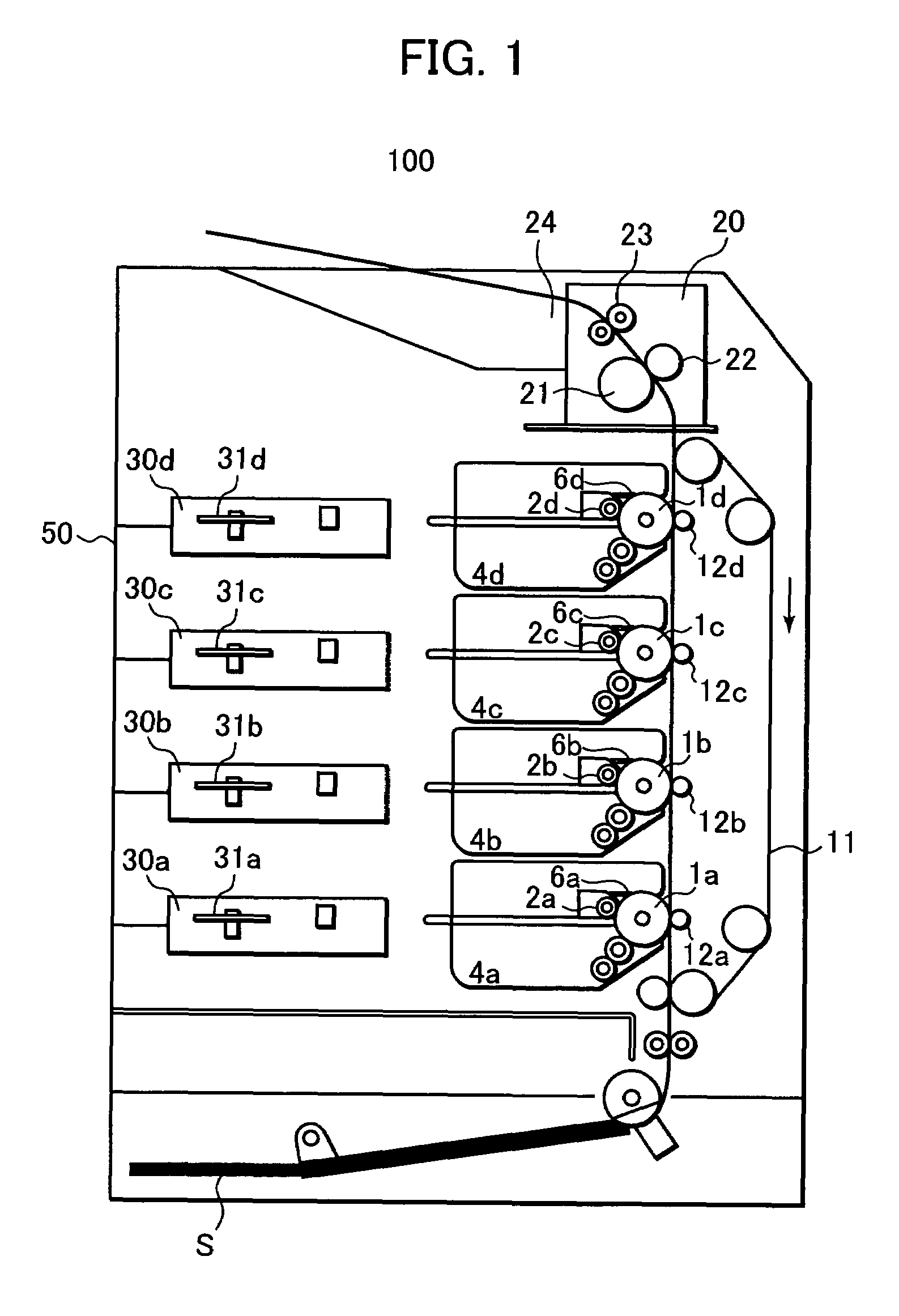
[0037]FIG. 1 is a sectional schematic view illustrating an essential configuration of an image forming apparatus in an exemplary embodiment of the present invention. The image forming apparatus 100 incorporates four electro-photographic conductor drums (which will be herein below referred to as “photoreceptor drums”) 1a, 1b, 1c, 1d for yellow, magenta, cyan and black, which serve as image bearing mediums and which are arranged linearly in a vertical direction in a parallel relation, and a conveyer belt 11 laid along the photoreceptor drums 1a to 1d, and serving as a transfer medium conveying unit for adsorbing thereto a recording sheet S as a transfer sheet which is adsorbed thereto through electrostatic adsorption.

[0038]Primary chargers 2a, 2b, 2c, 2d are arranged respectively around the photoreceptor drums 1a, 1b, 1c, 1d for uniformly charging the outer surfaces of the photoreceptor drums 1a to 1d, in the mentioned order from the upstream side in the rotating direction. Also, expo...

second exemplary embodiment

[0065]FIG. 9 is a sectional schematic view illustrating an exemplary configuration of the image forming apparatus in this embodiment. An image forming apparatus 101 has a similar configuration as that of the first embodiment shown in FIG. 1, except that a vibration detector system 51 serving as a vibration detecting unit is provided in the housing 50. It is noted that the detecting unit for a direction of weight imbalance and the phase control unit in the direction of weight imbalance are not provided in this embodiment.

[0066]Explanation will now be made of the relationship between the exposure units 30a to 30d and the housing 50 with reference to FIG. 10 which is a schematic plan view which shows the exposure units 30a to 30d which are supported at their left and right sides by a left side panel 52 and a right side panel 53 and at their rear sides by the housing 50.

[0067]Further, the polygon motor motors 31a to 31d are located at positions as shown in FIG. 10. Thus, vibration of th...


PUM


Abstract

An image forming apparatus is provided which includes a plurality of optical scanners, each including a rotating polygon mirror adapted to scan and expose a surface of an image bearing medium to create an electrostatic latent image on the surface in accordance with image data. The apparatus further includes a plurality of phase detectors, each assigned to a respective one of the plurality of optical scanners for detecting rotated phases of the rotating polygon mirrors. Moreover, the apparatus includes a rotated phase controller configured to control the rotated phases of the rotating polygon mirrors. The rotated phase controller is configured to control the rotated phases of the rotating polygon mirrors in accordance with results of detection by the plurality of rotated phase detectors so that rotated phase relationships of the rotating polygon mirrors are set to a predetermined pattern.

Description

BACKGROUND OF THE INVENTION[0001]1. Field of the Invention[0002]The present invention relates to an image forming apparatus such as a copying machine, a printer, a facsimile system or a composite OA (office automation) machine, and in particular, to an image forming apparatus adapted to aim at reducing noise during operation.[0003]2. Description of the Related Art[0004]An image forming apparatus such as a copying machine or a printer includes several movable components such as motors, gears, rollers and the like, which are incorporated in a paper feed portion, an image forming portion, a fixing portion and the like. These components cause vibration which is a source of noise. Further, this vibration also vibrates other components, resulting in more noise within the image forming apparatus.[0005]For example, a typical image forming apparatus may have a plurality of optical scanning units each having a polygon mirror motor which creates noise. Image writing positions of light beams co...

Claims


Application Information

Patent Timeline
Patent Type & Authority Patents(United States)
IPC IPC(8): H01J3/14H01J40/14H01J5/16
CPCG03G15/326G06K15/1219G06K15/129H04N1/047H04N1/1135H04N1/506G03G2215/0404H04N2201/04713H04N2201/04732H04N2201/04739H04N2201/04755G03G15/0435
Inventor FUKASE, YASUHIRO
Owner CANON KK
Why Eureka
Try Eureka