Thermoforming machine

a technology of thermoforming machine and thermoforming film, which is applied in the field of thermoforming machine, can solve the problems of poor appearance, time-consuming decorating methods, and the inability to pre-form imd film,

Inactive Publication Date: 2008-10-14
HON HAI PRECISION IND CO LTD
View PDF5 Cites 4 Cited by
  • Summary
  • Abstract
  • Description
  • Claims
  • Application Information

AI Technical Summary

Problems solved by technology

However, these decorating methods are time-consuming, and the resulting appearance is poor.
However, the IMD process has a number of drawbacks.
Firstly, IMD film cannot be preformed, and hence it is limited to flat or only slightly shaped products.
Secondly, IMD product design geometry is limited.
Thirdly, IMD film has a release carrier which needs to be removed.
However, it is a difficult to precisely control process which can result in deformation of the pre-forming film because of speed at which the film is stretched.

Method used


Image

  • Thermoforming machine
  • Thermoforming machine
  • Thermoforming machine

Examples


Embodiment Construction

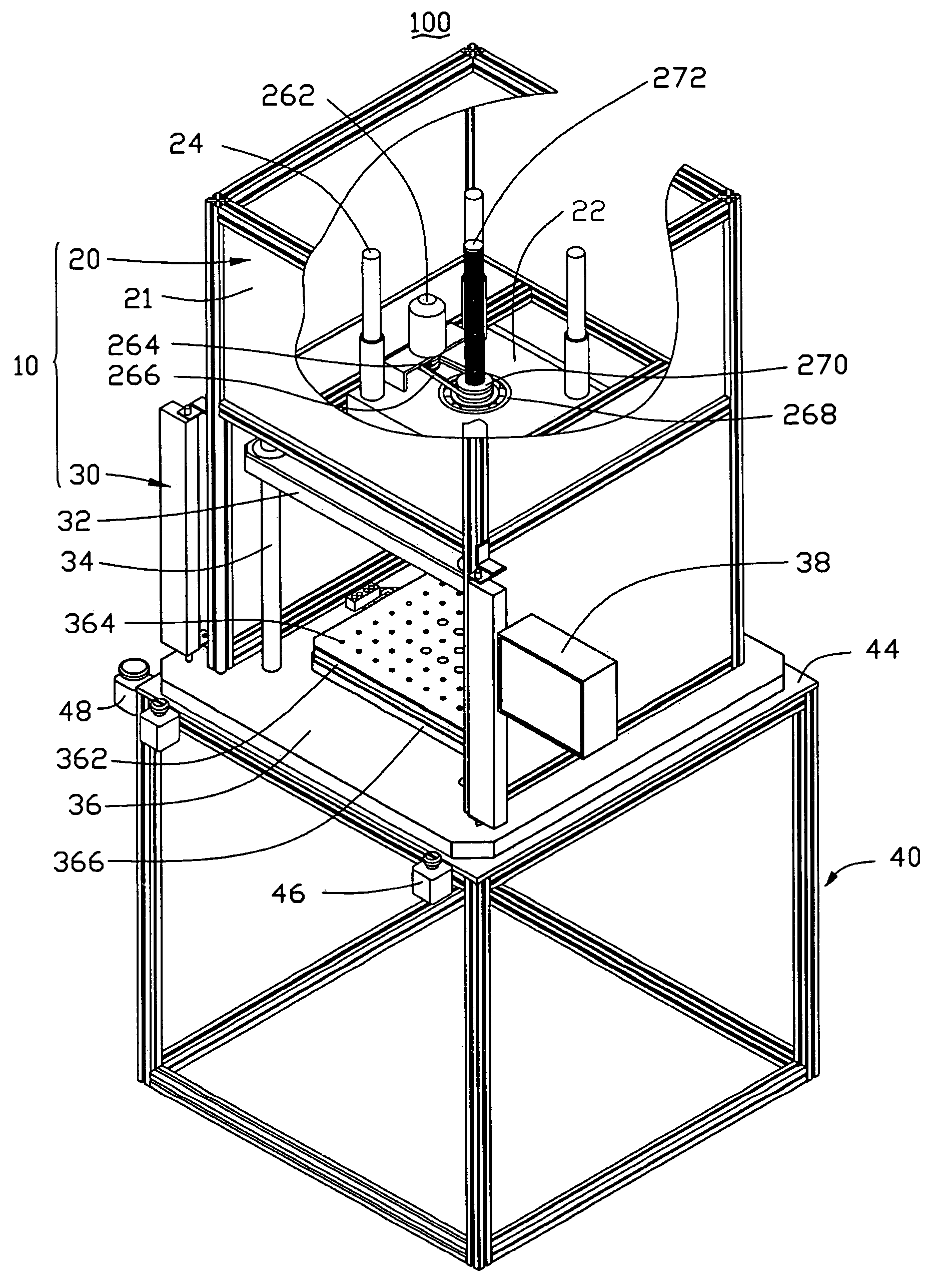
[0015]Referring now to the drawings, FIG. 1 shows a thermoforming machine 100 according to a preferred embodiment. The thermoforming machine 100 is adapted for pre-forming all kinds of flat film into a 3D film. The thermoforming machine 100 includes an upper frame 10 and a lower frame 40. The upper frame 10 and the lower frame 40 are made of Metal-Alumina-Silicon (MAS). A distance between a top of the upper frame 10 and a bottom of the lower frame 40 is 2300 millimeters.

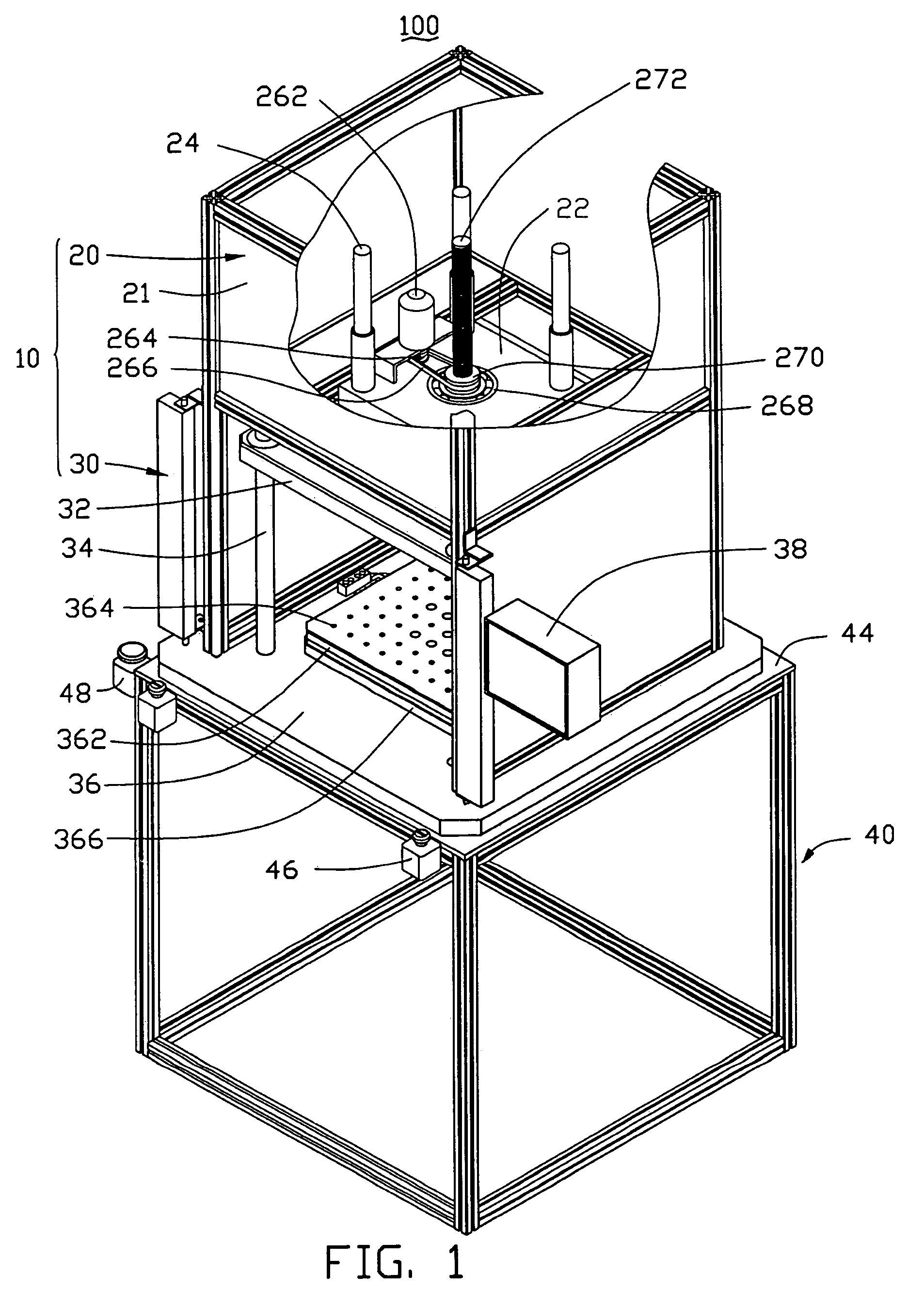
[0016]The upper frame 10 is cuboid shaped. The upper frame 10 includes a top bracket 20 and a bottom bracket 30. The top and bottom brackets 20, 30 are connected with each other via a square bracket (not labelled) therebetween. The top bracket 20 has a plate-like support member 22, four stand posts 24, and a driving mechanism (not labelled), all of which are disposed therein. In use, a top and three sides of the top bracket 20 are closed by close plate 21, and one side is open for facilitating operation. The driving ...


PUM

PropertyMeasurementUnit
distanceaaaaaaaaaa
lengthaaaaaaaaaa
distanceaaaaaaaaaa

Abstract

A thermoforming machine includes an upper frame (10) and a lower frame (40). The upper frame includes a top bracket (20) and a bottom bracket (30). The top bracket has a driving mechanism and a screw post (272) therein. The bottom bracket has an upper base plate (32) and a lower base plate (36) disposed with a distance therebetween. The upper base plate has a top forming plate (324) thereon. The lower base plate has a lower forming plate (362) thereon corresponding to the upper mold plate. One end of the screw post is fixed to the upper base plate, and the other end of the screw post is connected with the driving mechanism. The driving mechanism is for driving the screw post to bring the upper base plate moving toward or away the lower base plate.

Description

BACKGROUND OF THE INVENTION[0001]1. Field of the Invention[0002]The present invention relates to thermoforming machines, and particularly to a thermoforming machine which can be installed with various molds for forming a flat film onto a shaped mold.[0003]2. Discussion of the Related Art[0004]A traditional technology to decorate the plastic components is using post-molding techniques, including airbrushing, pad printing, painting, etc. However, these decorating methods are time-consuming, and the resulting appearance is poor. Therefore, in mold decoration (IMD) has been developed to decorate plastic components. A first decorating film is placed in a mold cavity in which the product is to be formed. A molten material is then injected into the mold cavity. The decorative film is attached to the surface of the molded product after a mold cavity containing the decorative film is injection molded. Thus, the decorative film needs to be accurately placed into position so that the decoratio...

Claims


Application Information

Patent Timeline
Patent Type & Authority Patents(United States)
IPC IPC(8): B28B3/00
CPCB29C51/38
Inventor PENG, JENG-CHILI, HENG-WEI
Owner HON HAI PRECISION IND CO LTD
Why Eureka
Try Eureka