Control circuit for displaying the same video simultaneously to two or more panels

a control circuit and video technology, applied in the field of display panel control circuits, can solve the problems of increasing the inability to control the display of the first and second panels simultaneously, and the inability to reduce the area of the entire lsi device, so as to prevent abnormal display effects

Inactive Publication Date: 2008-10-21
PANASONIC CORP
View PDF4 Cites 7 Cited by
  • Summary
  • Abstract
  • Description
  • Claims
  • Application Information

AI Technical Summary

Benefits of technology

[0023]If two VCOs and a double PLL loop are provided, simultaneous display of two panels is possible. However, the circuit size increases when the display panel control circuit is realized in the form of an integrated circuit, and the area of the entire LSI device cannot be reduced.
[0030]The display panel control circuit further comprises: a phase comparator for comparing the phase of an output signal of the first-panel horizontal system pulse generation section and the phase of a horizontal synchronization signal; and a smoothing element which receives a comparison result from the phase comparator to feed back a phase error voltage to the voltage controlled oscillator. With this structure, the PLL operates such that the reset timing of the first counter is equal to the timing of externally-input horizontal synchronization signal HD. Thus, the reset timing of the counter of the second-panel horizontal system pulse generation section can also be set equal to the timing of the horizontal synchronization signal. Therefore, abnormalities in display can be prevented.
[0032]The first counter outputs a PLL reset signal to the second frequency divider and the second counter. With this structure, the horizontal shift clock and the horizontal system output pulse for the second panel can be set to be in synchronization with the horizontal synchronization signal. Therefore, abnormalities in display can be prevented.
[0035]The display panel control circuit further includes a phase comparator for comparing the phase of an output signal of the first-panel horizontal system pulse generation section and the phase of a horizontal synchronization signal, and a smoothing element which receives a comparison result from the phase comparator to feed back a phase error voltage to the voltage controlled oscillator; and the control method further includes the step of resetting the first counter at a predetermined timing, and the step of resetting the second counter at the timing when the first counter is reset. With this structure, the PLL operates such that the reset timing of the first counter is equal to the timing of externally-input horizontal syncluonization signal HD. Thus, the reset timing of the counter of the second-panel horizontal system pulse generation section can also be set equal to the timing of the horizontal synchronization signal. Therefore, abnormalities in display can be prevented.

Problems solved by technology

Thus, the conventional display panel control circuit can alternately control display of the first panel and display of the second panel but cannot simultaneously control display of the first and second panels.
However, the circuit size increases when the display panel control circuit is realized in the form of an integrated circuit, and the area of the entire LSI device cannot be reduced.
None of the other prior documents discloses a control device or control circuit relating to simultaneous display of a plurality of liquid crystal panels.

Method used


Image

  • Control circuit for displaying the same video simultaneously to two or more panels
  • Control circuit for displaying the same video simultaneously to two or more panels
  • Control circuit for displaying the same video simultaneously to two or more panels

Examples


Embodiment Construction

[0046]Hereinafter, an embodiment of the present invention, which illustrates the best mode presently contemplated by the inventor(s) for carrying out the invention, is described in detail with reference to the drawings.

[0047]A liquid crystal display control circuit (display panel control circuit) according to an embodiment of the present invention is described with reference to FIGS. 1, 2 and 3. The liquid crystal display control circuit of this embodiment is used in an AV device (e.g., a digital video camera, a digital camera, or the like) having two liquid crystal panels.

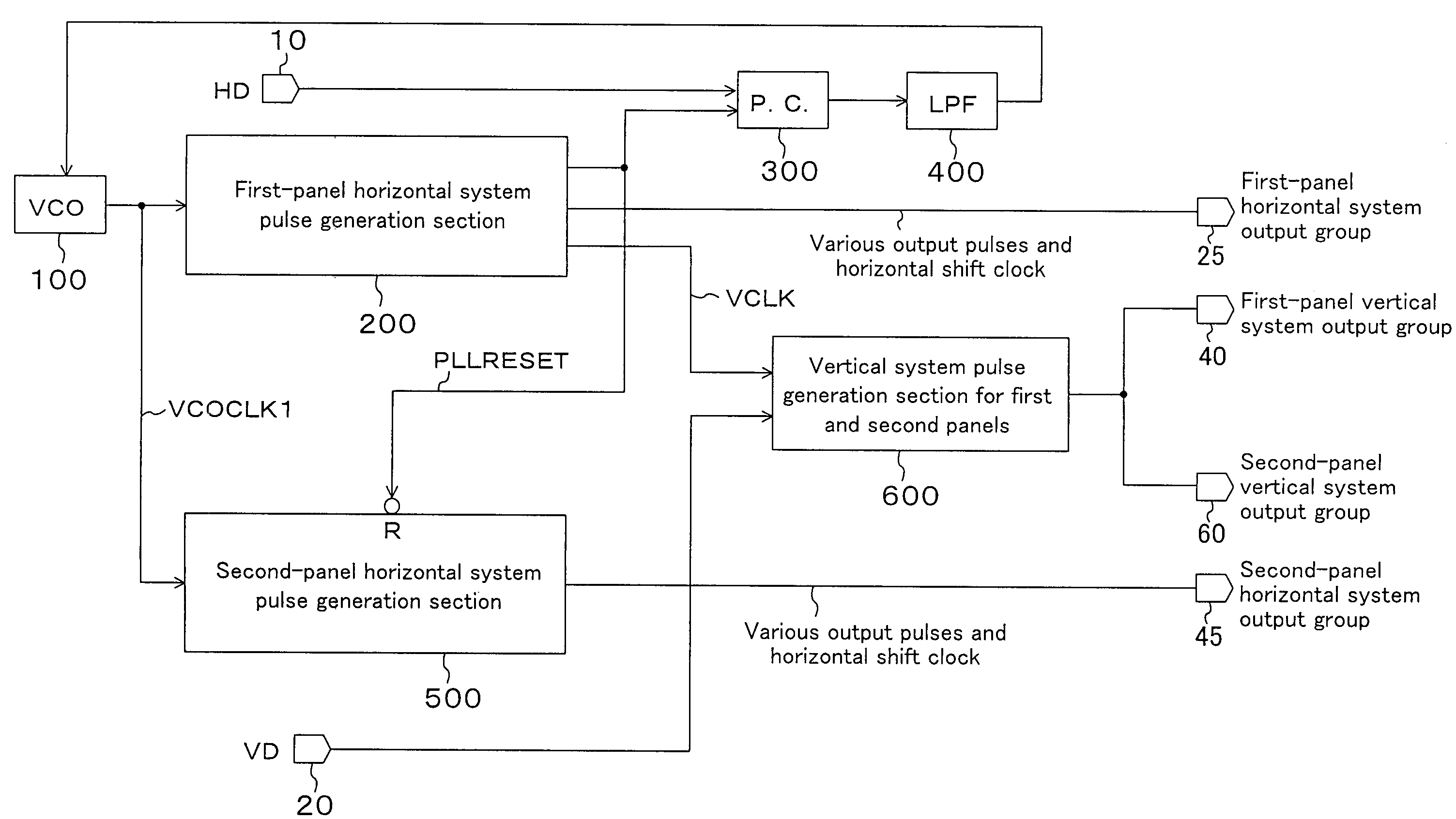
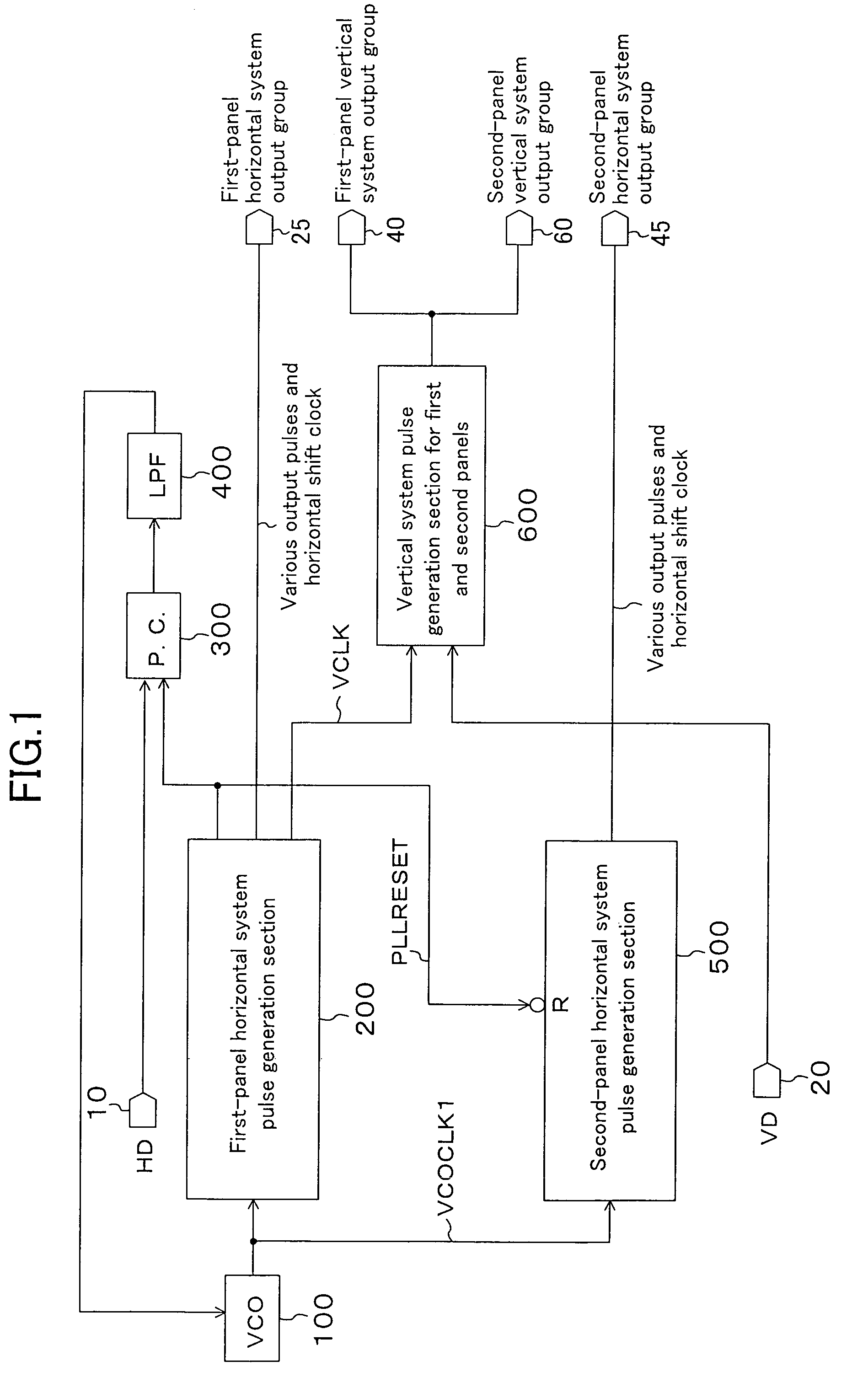
[0048]FIG. 1 is a block diagram showing a structure of a liquid crystal display control circuit according to an embodiment of the present invention.

[0049]As shown in FIG. 1, a liquid crystal display control circuit of the present embodiment includes a voltage controlled oscillator (VCO) 100, a first-panel horizontal system pulse generation section 200, a second-panel horizontal system pulse generation section 500,...


PUM


Abstract

A display panel control circuit includes a voltage controlled oscillator (VCO) for outputting a clock signal, a first-panel horizontal system pulse generation section, a second-panel horizontal system pulse generation section, a vertical system pulse generation section which is commonly used among the first and second panels, a phase comparator, and a smoothing element. The first-panel horizontal system pulse generation section and the second-panel horizontal system pulse generation section respectively generate a reference signal of a first-panel horizontal system output group and a reference signal of a second-panel horizontal system output group from signal VCOCLK1 output from the VCO. Thus, it is possible to simultaneously drive two different panels.

Description

CROSS-REFERENCE TO RELATED APPLICATION[0001]This application claims priority under 35 U.S.C. §119(a) on Japanese Patent Application No. 2004-1650 filed on Jan. 7, 2004, the entire contents of which are hereby incorporated by reference.BACKGROUND OF THE INVENTION[0002]1. Field of the Invention[0003]The present invention relates to a display panel control circuit for controlling the operation of a display panel, such as a liquid crystal panel, or the like, and specifically to a display panel control circuit for simultaneously driving two display panels which operate based on different driving methods.[0004]2. Description of the Prior Art[0005]The liquid crystal display device which displays images using so-called liquid crystals has been widespread. For example, the liquid crystal display device, which includes a control circuit of a liquid crystal panel, is incorporated in a digital video camera (DVC), a digital still camera (DSC), or other AV devices.[0006]A conventional liquid crys...

Claims


Application Information

Patent Timeline
Patent Type & Authority Patents(United States)
IPC IPC(8): G09G5/00G06F3/14G09G3/36G09G5/14H04N5/66H04N5/93
CPCG06F3/1423G09G5/008G09G3/3611
Inventor KINUGASA, NORIHIDENIRASAWA, YOSHIOHAMAGUCHI, HIDEOOTA, SACHI
Owner PANASONIC CORP
Why Eureka
Try Eureka