Method and apparatus for modeling and analyzing MPLS and virtual private networks

a virtual private network and model-based label switching technology, applied in the field of computer networks, can solve the problems of inability to capture the relationship between a vpn routing and forwarding table (vrf) and a route target, and the network model that has been employed, and achieve the effect of capturing the relationship between a vpn routing and forwarding table and a route target, and a vpn. the problem of network model limitations

Active Publication Date: 2008-10-21
EMC IP HLDG CO LLC
View PDF7 Cites 36 Cited by
  • Summary
  • Abstract
  • Description
  • Claims
  • Application Information

AI Technical Summary

Problems solved by technology

However, the ability to analyze MPLS networks and VPNs has been limited by the network models that have been employed.
For example, one cannot easily capture the relationship between a VPN Routing and Forwarding Table (VRF) and a Route Target (RT).
However, MIBs typically do not capture relationships between objects.
The lack of a systematic model specifically suited for the MPLS and VPN object classes and their relationships limits several forms of important analysis.

Method used


Image

  • Method and apparatus for modeling and analyzing MPLS and virtual private networks
  • Method and apparatus for modeling and analyzing MPLS and virtual private networks
  • Method and apparatus for modeling and analyzing MPLS and virtual private networks

Examples


Embodiment Construction

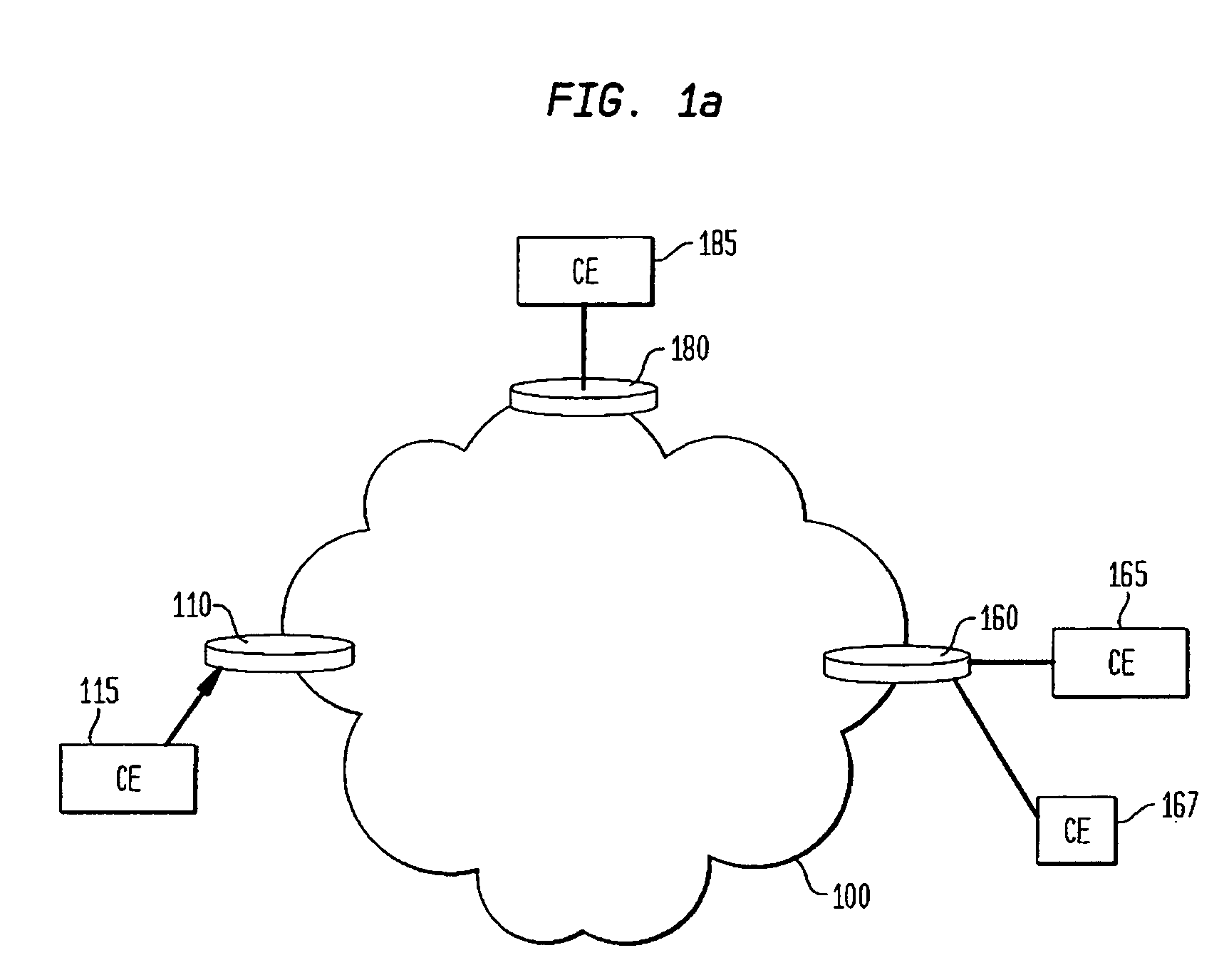
[0022]FIG. 1a illustrates an exemplary representation of a virtual private network 100 composed of components, referred to as provider edge routers (PE), 110, 160 and 180 that represent the means for providing information items to, and receiving information items from, network 100. Also shown are Customer Edge (CE) nodes or routers 115, 165, 167 and 185, which are in communication with corresponding provider edge nodes 110, 160 and 180. The CE nodes 115, 165, 167 and 185 represent are components or routers located at the customer premises that are directly connected, at either a network Layer 2 or Layer 3 level (of the OSI stack) to the ingress and egress provider edge routers 110, 160 and 180. Internal routers, which are not shown, are responsible for converting the packet or frame structure from the one used to communicate with CE routers 115, 165, 167, and 185 to the packet or frame structure used internally by an associated private network.

[0023]A CE router or node is typically ...


PUM


Abstract

A method and apparatus for representing a network and performing operations on the represented network are disclosed. The method comprises the steps of creating at least one configuration non-specific object class associated with components of the network, creating at least one configuration non-specific representation of relationships among associated object classes, representing a behavior relationship among the object classes based on the representations of the relationships among the object classes and analyzing properties of the network based on the behavior relationships. In aspects of the invention, the represented network may be an MPLS network, a VPN or a combined MPLS-VPN.

Description

CLAIM OF PRIORITY[0001]This application claims the benefit, pursuant to 35 USC §119(e), of the earlier filing date of U.S. Provisional Patent Application Ser. No. 60 / 505,802, entitled “Model-Based Discovery of Multi-Protocol Label Switching Virtual Private Networks, filed on Sep. 25, 2003, the contents of which are incorporated by reference herein.RELATED APPLICATIONS[0002]This application is related to concurrently-filed:[0003]U.S. patent application Ser. No. 10 / 950,150, entitled “Model-Based Method and Apparatus for Determining Virtual Private Network Topologies;” and[0004]U.S. patent application Ser. No. 10 / 949,589, entitled “Model-Based Method and Apparatus for Determining MPLS Network Properties,” the contents of both of which are incorporated by reference herein.FIELD OF THE INVENTION[0005]The invention relates generally to computer networks, and more specifically to methods and apparatus for modeling and analyzing Model-Based Multi-Protocol Label Switching (MPLS) networks and...

Claims


Application Information

Patent Timeline
Patent Type & Authority Patents(United States)
IPC IPC(8): G06F15/16G06FG06F11/00H04L9/00
CPCH04L41/0233H04L45/00H04L45/02H04L41/122H04L45/033
Inventor BENJAMIN, SHAIFLORISSI, PATRICIAKUHHIRTE, WILLIAMHE, LIDA
Owner EMC IP HLDG CO LLC
Why Eureka
Try Eureka