Eureka AIR delivers breakthrough ideas for toughest innovation challenges, trusted by R&D personnel around the world.

Multipoint ignition device

a multi-point ignition and ignition device technology, applied in the direction of spark plugs, machines/engines, mechanical equipment, etc., can solve the problem of ignition before the spark fly

Active Publication Date: 2008-10-28
MIYAMA
View PDF9 Cites 14 Cited by
  • Summary
  • Abstract
  • Description
  • Claims
  • Application Information

AI Technical Summary

Benefits of technology

[0006]According to this invention, a part of the intermediate member connected to the electrode pair is exposed to the opening, which constitutes a part of a combustion chamber. Hence, by adjusting the exposure area of the intermediate member, the amount of heat received by the multipoint ignition device from the combustion gas can be adjusted, whereby the heat value of the multipoint ignition device can be adjusted.

Problems solved by technology

Conversely, when the temperature of the electrode pair rises excessively, the electrode pair itself becomes a heat source, and therefore pre-ignition occurs, causing ignition before the spark flies.

Method used


Image

  • Multipoint ignition device
  • Multipoint ignition device
  • Multipoint ignition device

Examples


Embodiment Construction

[0010]An embodiment of this invention will be described below with reference to the attached drawings.

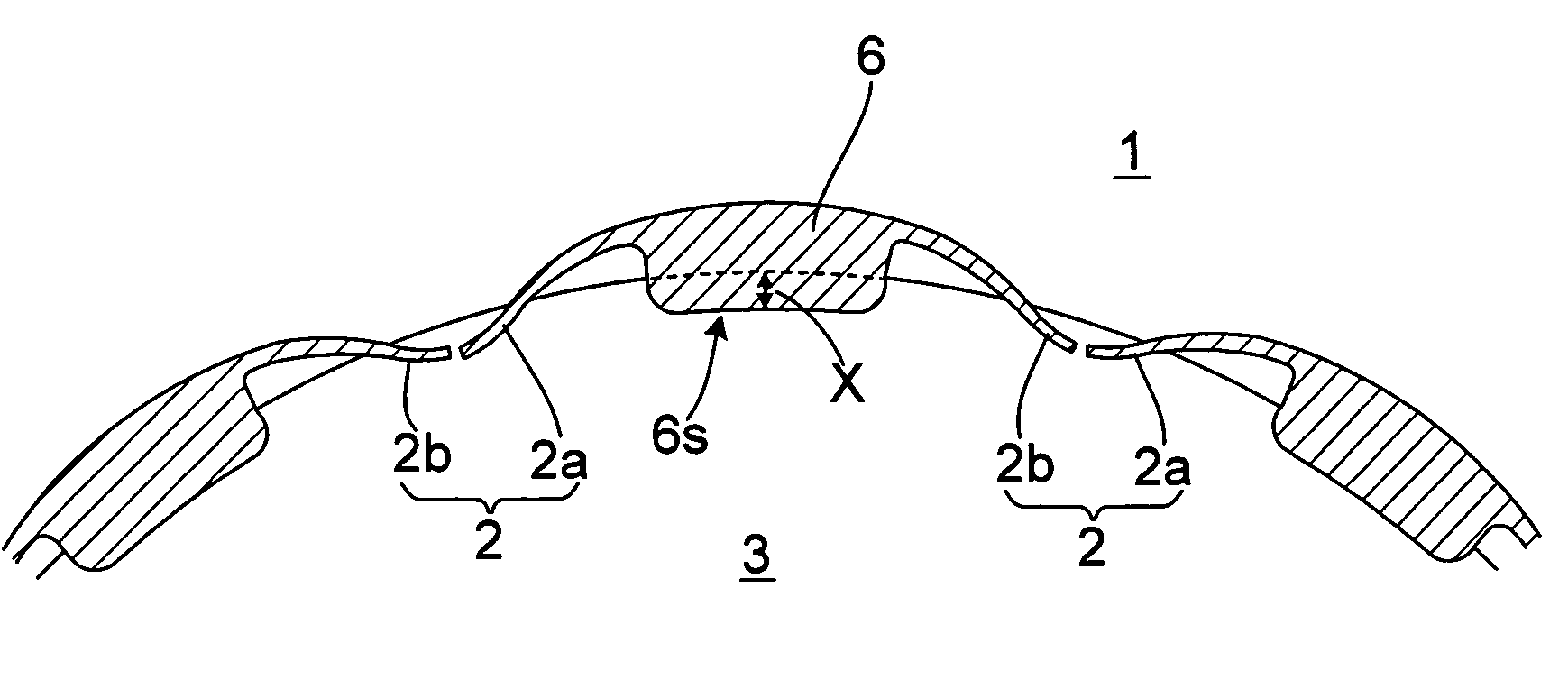
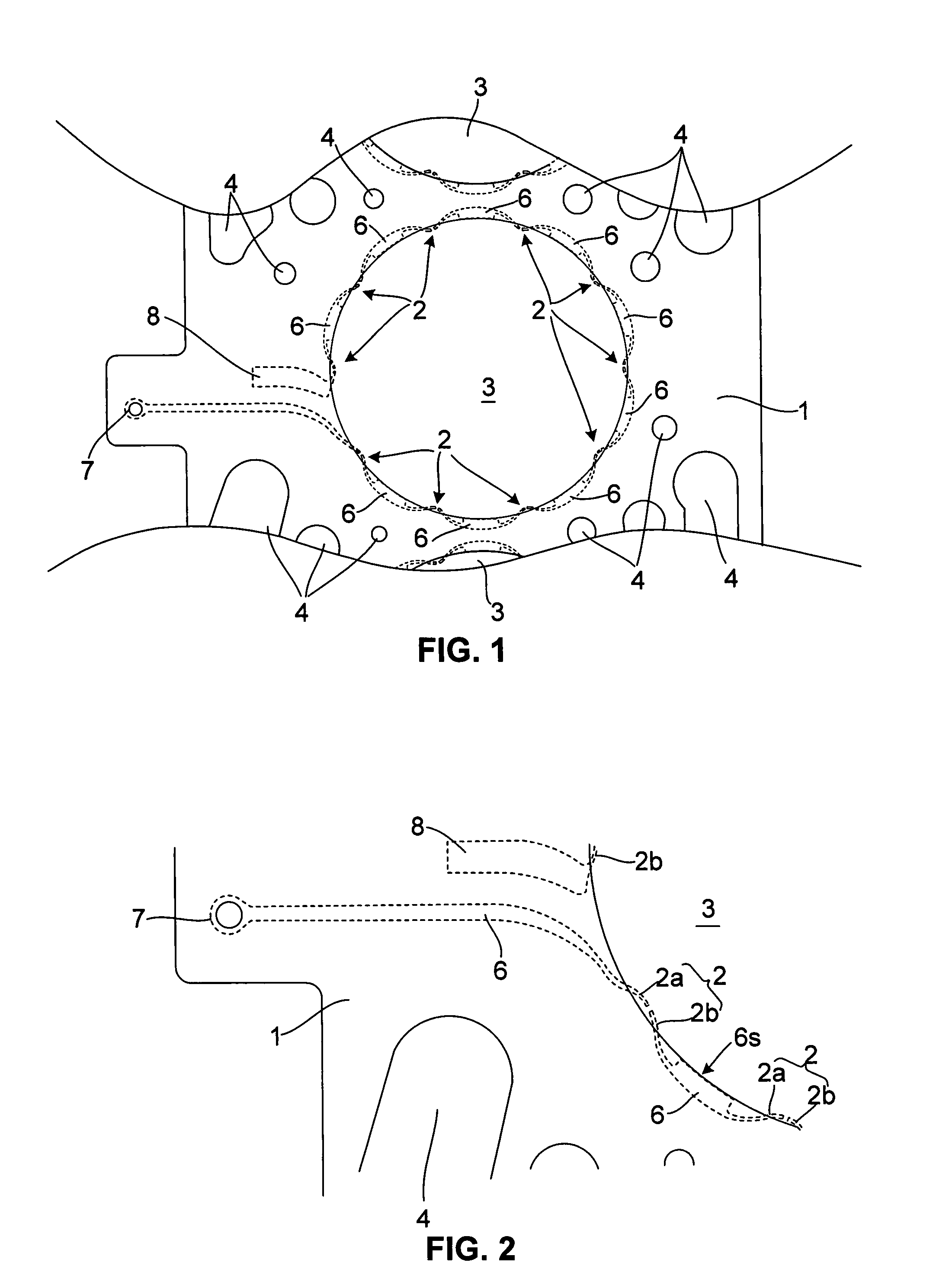
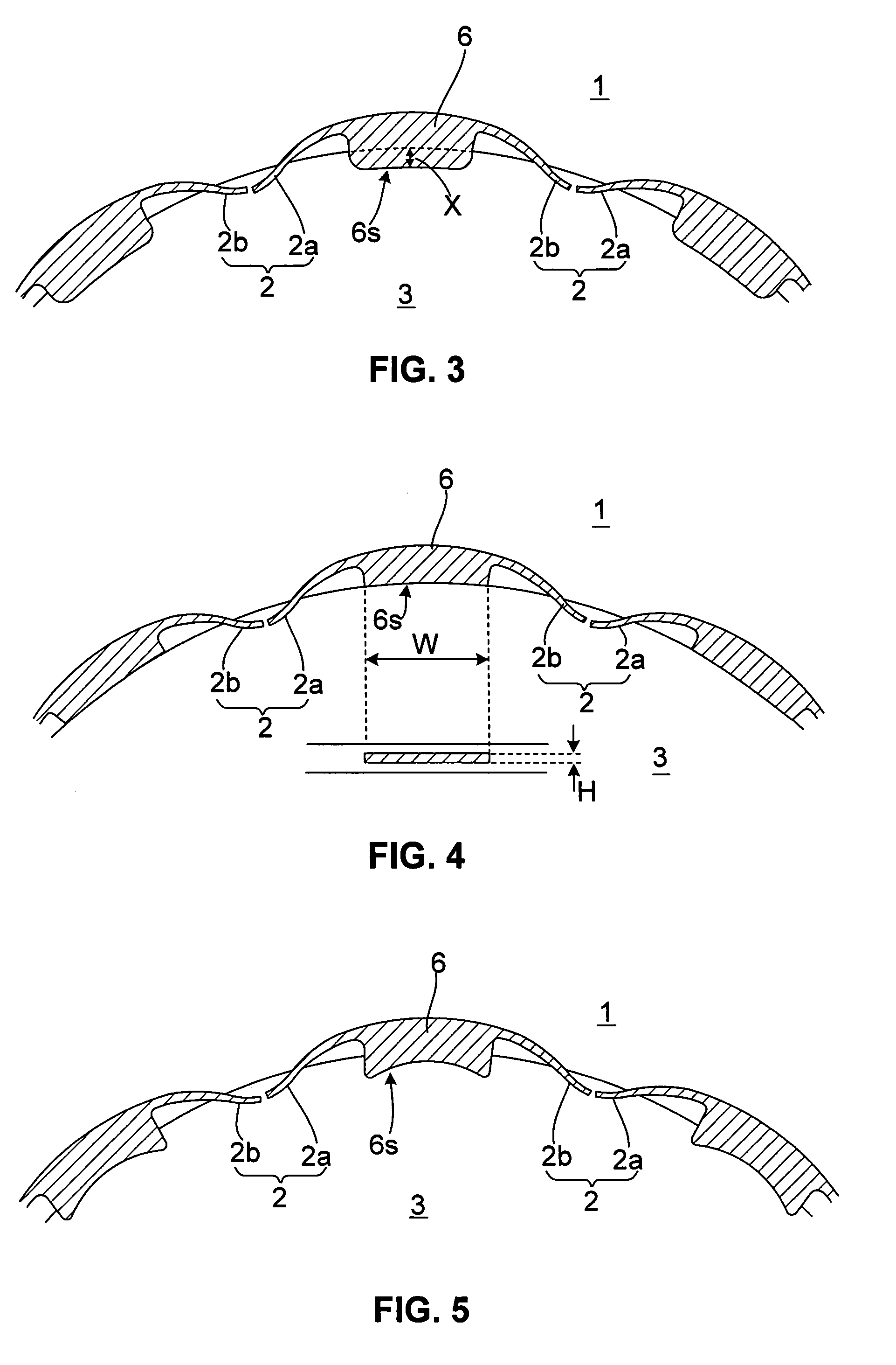
[0011]FIG. 1 shows the constitution of a multipoint ignition device according to this invention, and FIG. 2 is a partially enlarged view thereof. In this embodiment, a multipoint ignition device is formed integrally with a head gasket 1 of an engine, and when the multipoint ignition device is sandwiched between a cylinder head and a cylinder block of the engine, a plurality of electrode pairs 2 are disposed around a cylinder opening portion. Each electrode pair 2 is constituted by a current-carrying electrode 2a and an earth electrode 2b, and an ignition gap is formed between the electrodes 2a, 2b.

[0012]The head gasket 1 is formed with a plurality of openings 3, 4. The largest, central opening 3 has a substantially identical diameter to the cylinder opening portion, and is formed in a position corresponding to the cylinder opening portion so as to form a part of a side wall of a co...


PUM


Abstract

A multipoint ignition device comprises: a head gasket (1) interposed between a cylinder head and a cylinder block of an engine, having an opening (3) in a position corresponding to a cylinder opening portion; and a plurality of intermediate members (6) connected respectively to a plurality of electrode pairs (2) and held by the head gasket (1). A part of at least one of the plurality of intermediate members (6) is exposed to the opening (3).

Description

TECHNICAL FIELD OF THE INVENTION[0001]This invention relates to a multipoint ignition device used in a multipoint ignition engine having a plurality of ignition gaps in a single combustion chamber.BACKGROUND OF THE INVENTION[0002]JP2-123281A and JP1-193080A disclose a multipoint ignition engine in which a plurality of electrode pairs constituting ignition gaps are disposed around a cylinder opening portion of an engine such that an air-fuel mixture in a combustion chamber is ignited from the plurality of ignition gaps. According to this constitution, in comparison with a case in which ignition is performed using a conventional spark plug that performs ignition only from the center of the combustion chamber, combustion of the air-fuel mixture in a peripheral edge portion of the combustion chamber is promoted, enabling improvements in engine output and fuel economy.SUMMARY OF THE INVENTION[0003]When the temperature of the electrode pair is lower than a self-cleaning temperature, carbo...

Claims


Application Information

Patent Timeline
IPC IPC(8): F02P15/08F02P13/00F02P15/10
CPCF02P13/00F02P15/08
Inventor MINAMI, KATSUAKI
Owner MIYAMA
Why Eureka
Eureka Blog
Learn More