ITE hearing aid for binaural hearing assistance

a technology for hearing aids and binaural hearing, applied in deaf-aid sets, electrical devices, etc., can solve the problem of little installation space available, and achieve the effect of simple assembly and stable fastening of the antenna devi

Active Publication Date: 2008-10-28
SIVANTOS PTE LTD
View PDF13 Cites 14 Cited by
  • Summary
  • Abstract
  • Description
  • Claims
  • Application Information

AI Technical Summary

Benefits of technology

[0011]According to the invention, for communication between the two hearing aids for binaural assistance, the antenna is fitted in a precisely defined position, i.e. at a specific angle in relation to the housing in the ITE hearing aid. In this way, energy-saving transmission between the two ITE hearing aids can be achieved, since the directions of transmission of the respective antennas of the two hearing aids are made to match each other.
[0012]The antenna device preferably has an antenna coil. With this antenna coil it is possible to build up an electromagnetic transmission path between the two hearing aids in the case of binaural hearing assistance.
[0015]A battery spring for the contacting of a hearing aid battery may be used as a holding means for the antenna device. For this purpose, an extension arm to which the antenna device can be fastened is attached to the battery spring. In this way, stable fastening of the antenna device can be ensured.
[0016]Alternatively, the fastening of the antenna device may take place on the programming contacts of the hearing aid. For this purpose, a special adapter to which the antenna device is fastened or can be fastened is fitted on the programming contacts. This fastening possibility may be of advantage in the case of specific hearing aid constructions if installation space for the antenna device is only available in the region of the programming contacts. In addition, this fastening variant has the advantage of simple assembly.

Problems solved by technology

In the case of ITE hearing aids, there is the fundamental problem that only little installation space is available.

Method used


Image

  • ITE hearing aid for binaural hearing assistance
  • ITE hearing aid for binaural hearing assistance
  • ITE hearing aid for binaural hearing assistance

Examples


Embodiment Construction

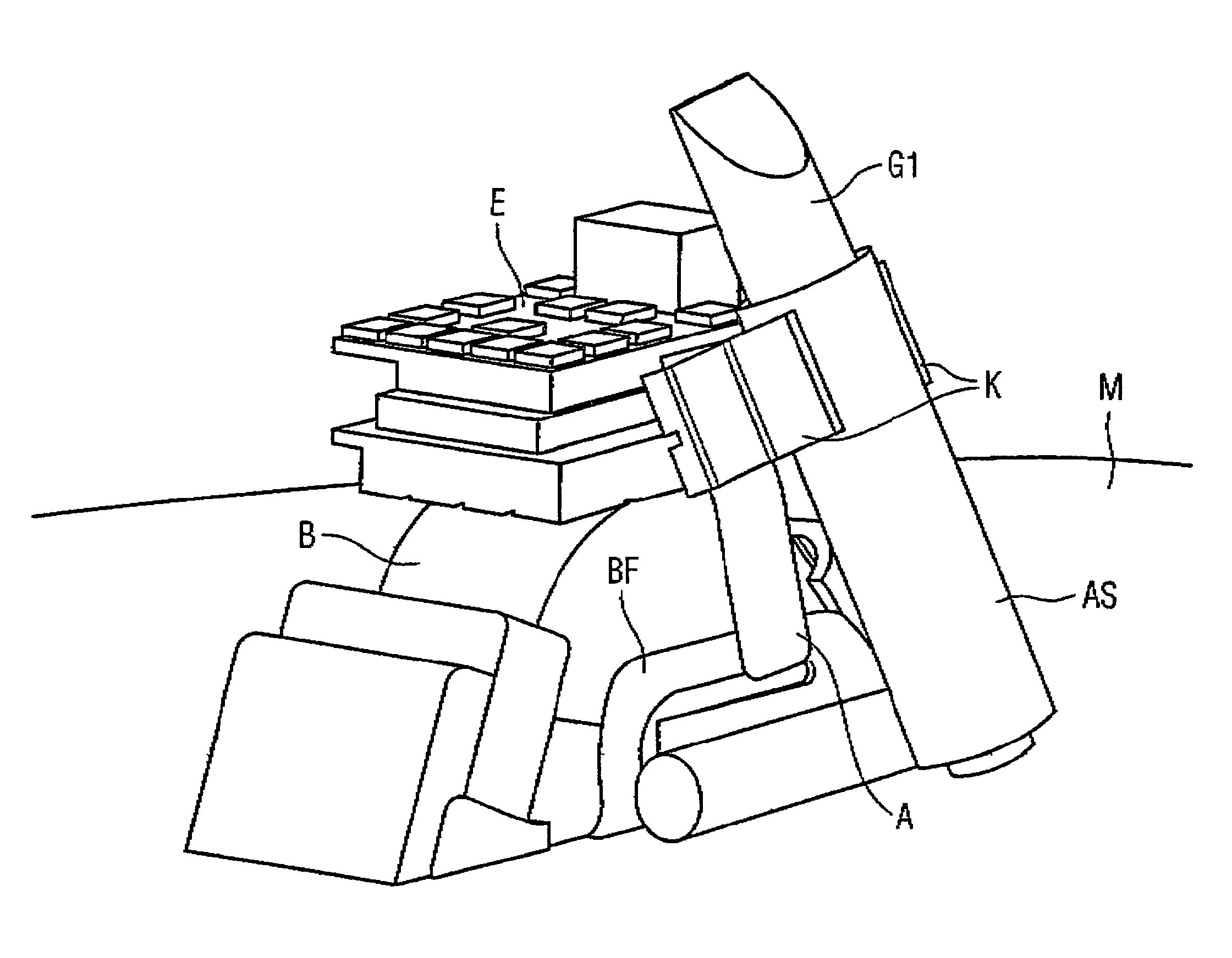
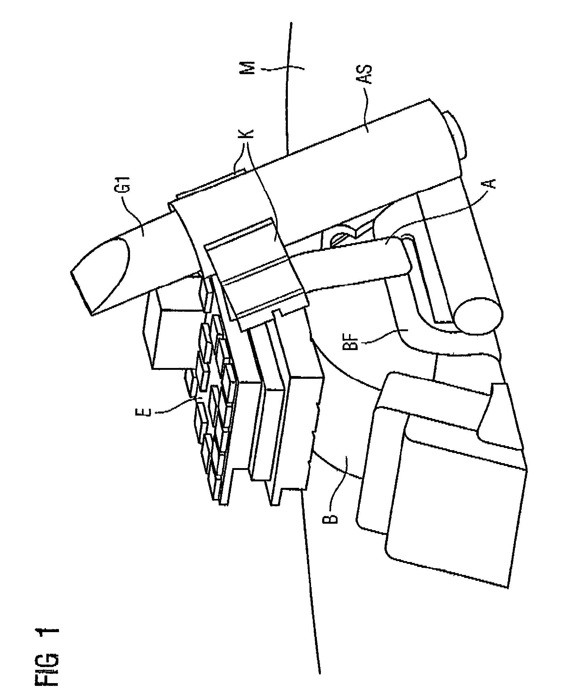
[0019]As shown in FIG. 1, electronic components of the hearing aid are fastened on a mounting plate M, which in the final state during the production of the hearing aid is individually cut to match the contour of the ear adapter and is referred to as a face plate. In particular, the battery B protrudes through the mounting plate M. It is held by a battery spring BF. Indicated above the battery B is an electronics module E.

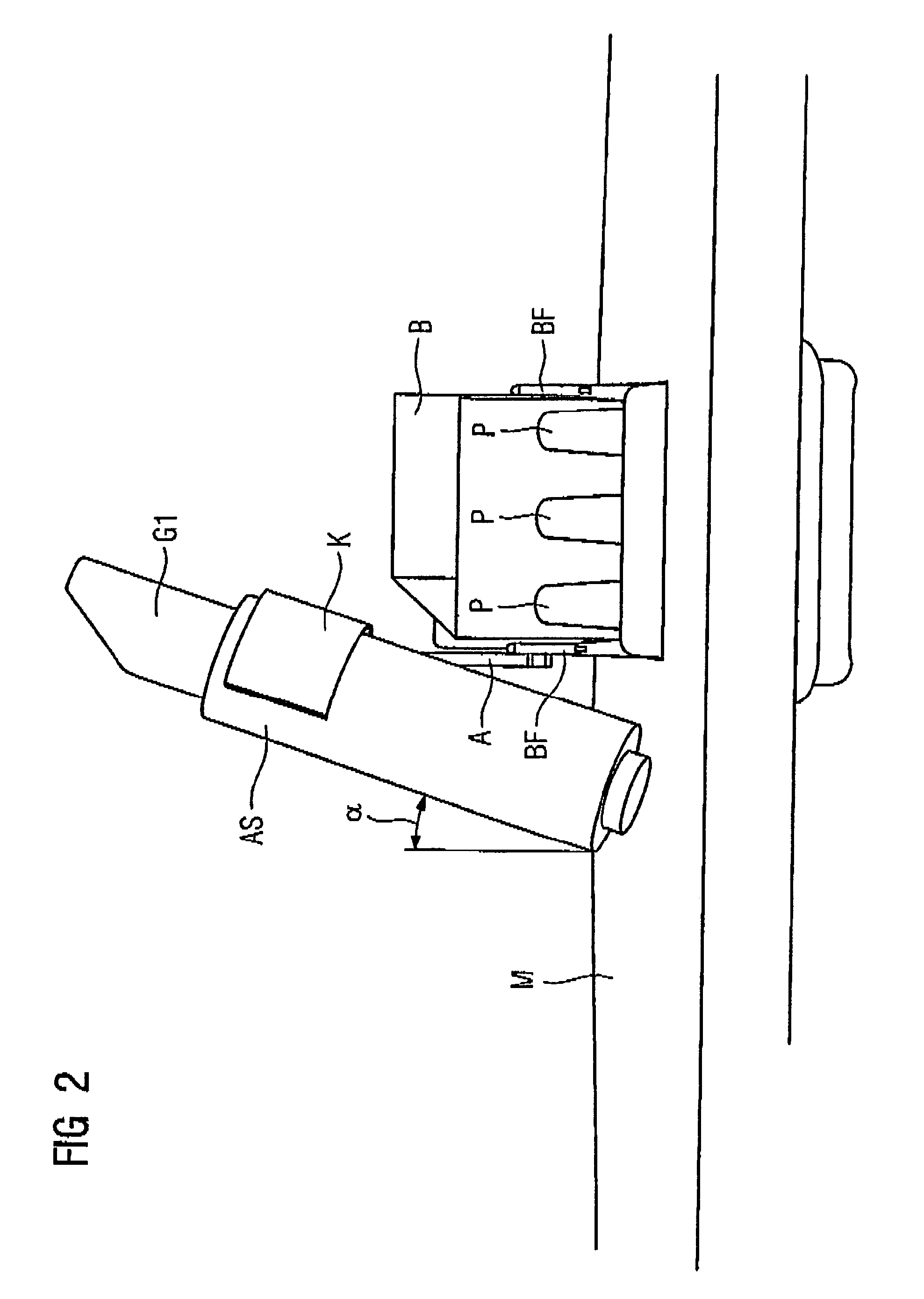
[0020]Fastened to the battery spring BF is an extension arm A, on the distal end of which a clip K is mounted. The clip K holds an antenna coil AS. As a spacer with respect to the loudspeaker, a piece of soft rubber G1 is provided on the end face of the antenna coil AS, which face is in the vicinity of the clip K.

[0021]As can likewise be seen from FIG. 1, the extension arm A is angled away approximately in the region of its center, so that the desired angular position of the antenna coil AS with respect to the mounting plate is achieved. The fastening of the extens...


PUM


Abstract

Between ITE hearing aids for binaural hearing assistance, energy-saving communication is made possible by disposing an antenna device with a preferred direction of transmission in the hearing aid housing such that, in a state in which the hearing aid is attached to or inserted one ear of the patient, the preferred direction of transmission is substantially toward the other ear of the patient. In this way it is ensured that the directions of transmission of the two hearing aids in the fitted state lie substantially on a straight line, so that optimum transmission can be achieved.

Description

[0001]This application claims the benefit of U.S. Provisional Application No. 60 / 557,880, filed Mar. 31, 2004.BACKGROUND OF THE INVENTION[0002]1. Field of the Invention[0003]The present invention relates to an ITE (in the ear) hearing aid for binaural hearing assistance to a patient, of the type having a housing and an antenna device that has a preferred direction of transmission.[0004]2. Description of the Prior Art[0005]In the case of ITE hearing aids, there is the fundamental problem that only little installation space is available. Therefore, the components that are necessary in ITE hearing aids have to be made as small as possible and / or reduced in number to a minimum.[0006]With binaural hearing assistance, there is also the requirement that the two hearing aids must be made to match each other in their settings. If the ITE hearing aids have arrangements that set themselves automatically to specific hearing situations, the setting of the two hearing aids should take place in su...

Claims


Application Information

Patent Timeline
Patent Type & Authority Patents(United States)
IPC IPC(8): H04R25/00
CPCH04R25/552H04R25/554H04R2225/51
Inventor NIEDERDRANK, TORSTENSAUER, JOSEPHSCHMITT, CHRISTIAN
Owner SIVANTOS PTE LTD
Why Eureka
Try Eureka