Method and device for frame synchronization in communication systems

a communication system and frame synchronization technology, applied in the telecommunications sector, can solve problems such as poor performance of current frame synchronization methods

Inactive Publication Date: 2018-06-28
FUNDACIO PRIVADA CENT TECNOLOGIC DE TELECOMUNICACIONS DE CATALUNYA
View PDF1 Cites 0 Cited by
  • Summary
  • Abstract
  • Description
  • Claims
  • Application Information

AI Technical Summary

Benefits of technology

[0031]The invention can be applied to channels with soft output, i.e. with a received signal which is a real or complex number or a quantized version of a real or complex number, e.g., a binary-input AWGN channel. The invention can be easily extended from BPSK to higher-order J-PSK signalling, J≥2.

Problems solved by technology

In these cases, the current approach for frame synchronization has poor performance.

Method used


Image

  • Method and device for frame synchronization in communication systems
  • Method and device for frame synchronization in communication systems
  • Method and device for frame synchronization in communication systems

Examples


Embodiment Construction

[0054]The matters defined in this detailed description are provided to assist in a comprehensive understanding of the invention. Accordingly, those of ordinary skill in the art will recognize that variation changes and modifications of the embodiments described herein can be made without departing from the scope and spirit of the invention. Also, description of well-known functions and elements are omitted for clarity and conciseness.

[0055]Of course, the embodiments of the invention can be implemented in a variety of architectural platforms, operating and server systems, devices, systems, or applications. Any particular architectural layout or implementation presented herein is provided for purposes of illustration and comprehension only and is not intended to limit aspects of the invention.

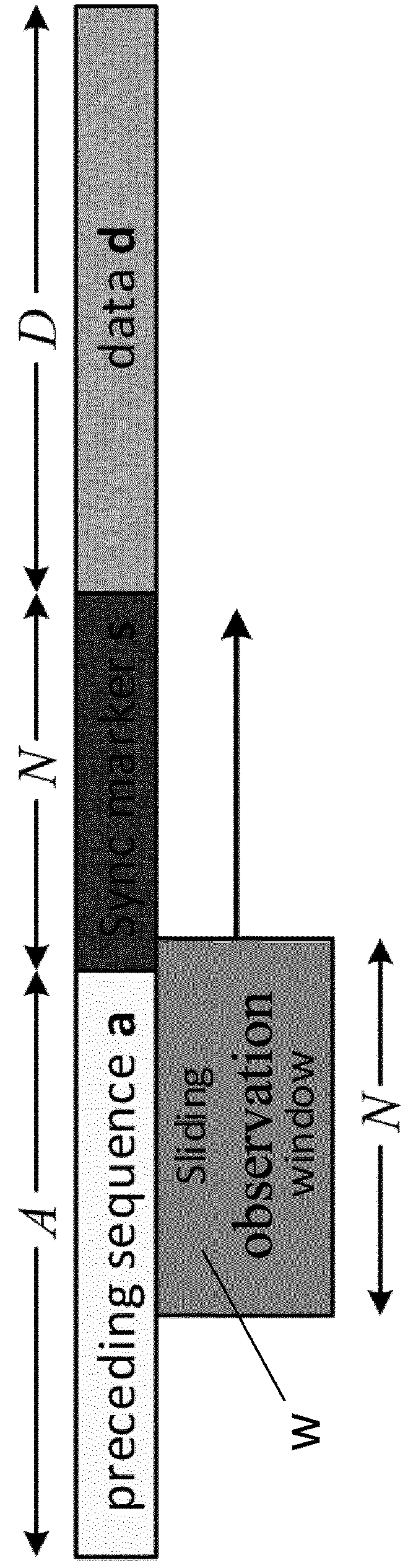
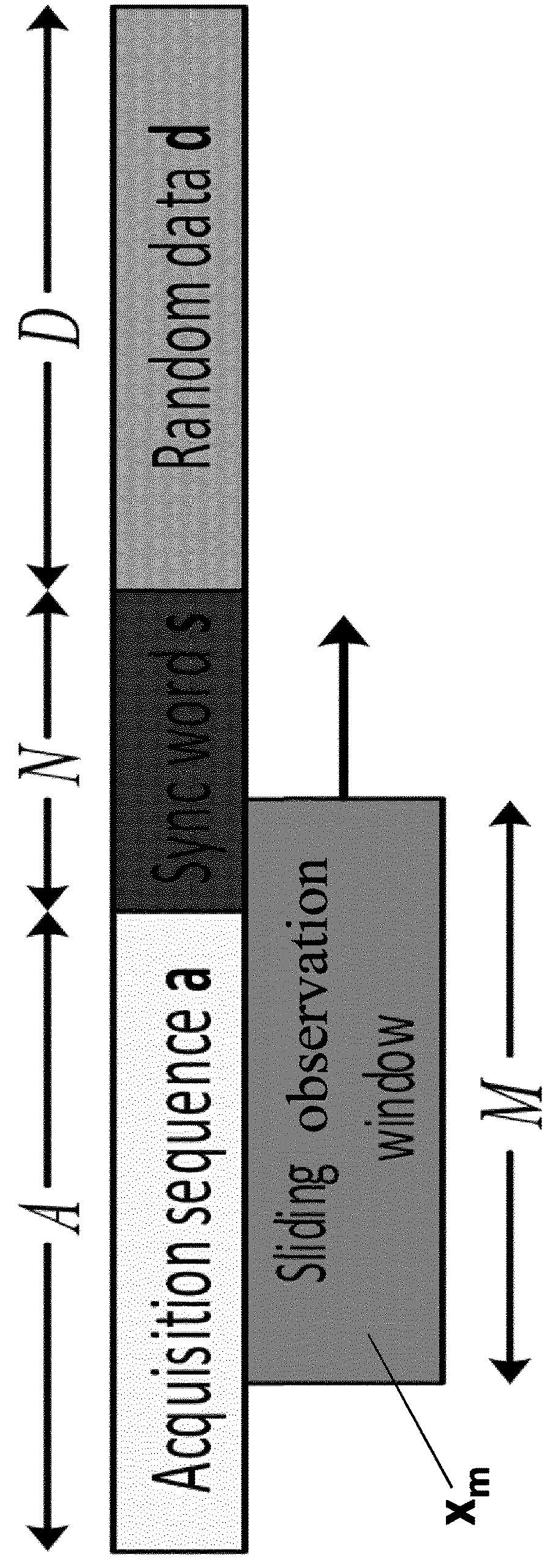
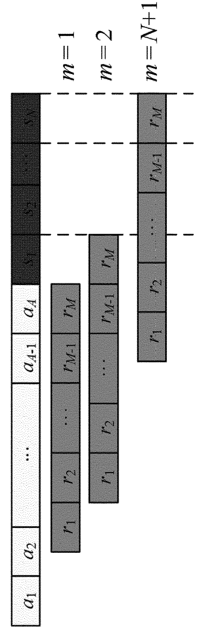
[0056]FIG. 1 illustrates transmitted data in a frame whose structure consists of: a sync marker (s) which is a known word of length N and indicates the beginning of the data (d) transmitted withi...


PUM


Abstract

A device and method for frame synchronizing in a receiver of a communication system. The frame, transmitted in a signal out of a J-PSK constellation, J≥2, is received including a data sequence, a synchronization marker preceding the data sequence and an acquisition sequence preceding the synchronization marker, and wherein the synchronization marker is searched by using the acquisition sequence. In addition, a sliding observation window with an extended length, being M≥N can be used. Also, a buffer-based peak detection to find the synchronization marker in a buffered span of received symbols can be used, in addition to list decoding in order to exploit the error detection capability of the channel decoding in the receiver for false alarm detection.

Description

FIELD OF THE INVENTION[0001]The present invention has its application within the telecommunication sector, especially, deals with the field of frame synchronizers in digital communication systems.[0002]More specifically, the present invention proposes a method and a receiver device to optimize frame synchronization in (wireless or wired) communication systems, especially in deep-space communications.BACKGROUND OF THE INVENTION[0003]In many digital communication systems, the transmitted data is organized in frames, wherein the beginning of the data, which is of interest to the receiver, is indicated by a known synchronization (sync) marker. Before the sync marker, another sequence with certain known characteristics is transmitted. This sync marker is a sequence of known symbols which directly precedes the data and helps the receiver to determine the beginning of the data.[0004]Frame synchronization is therefore an important receiver function which has to be performed before decoding ...

Claims


Application Information

Patent Timeline
Patent Type & Authority Applications(United States)
IPC IPC(8): H04L27/26H04L7/04
CPCH04L27/2692H04L7/041H04L27/2656H04L27/2675H04L27/2671H04L27/2663H04J3/0608H04L7/00
Inventor PFLETSCHINGER, STEPHANNAVARRO RODERO, MONICACLOSAS GOMEZ, PAU
Owner FUNDACIO PRIVADA CENT TECNOLOGIC DE TELECOMUNICACIONS DE CATALUNYA
Why Eureka
Try Eureka