Insulation for a universal cross joint

a cross-joint, universal technology, applied in the direction of rotary bearings, rolling contact bearings, shafts and bearings, etc., can solve the adverse effects of acoustic or mechanical nature on the driver, damage to the drive train or the steering column, and no insulation whatsoever is effected against low-frequency vibrations, etc., to achieve large axial compliance of the joint, reduce vibration, and reduce vibration.

Inactive Publication Date: 2008-11-04
FORD GLOBAL TECH LLC
View PDF13 Cites 7 Cited by
  • Summary
  • Abstract
  • Description
  • Claims
  • Application Information

AI Technical Summary

Benefits of technology

[0022]Thus, the rotational compliance of the joint may be minimal in one embodiment of the insulating element or elements. A large rotational compliance, for example, in a motor vehicle steering column, causes a “spongy” steering behavior that can be avoided with the large rotational stiffness that can be realized in the universal joint according to the invention.
[0023]At the same time, a large axial compliance of the joint at a large rotational stiffness can be achieved, which, for example, can be utilized in a motor vehicle steering column for the advantageous filtering of stimuli from the road. The minimization of the axial stiffness of the universal joint at a large rotational stiffness is realized in an optimal manner by the maximized distance of the insulation elements, namely at the bearing positions in the respective joint yoke.
[0027]Surprisingly, it became apparent due to the arrangement according to the invention of the insulation element or elements, on the one hand, between the bearing and the yoke arm and, on the other hand, between the bearing and the pin, that a particularly effective uncoupling, with regard to acoustics and vibration dynamics, of the shafts connected to each other is achieved. Further, the insulation elements are subjected to a comparatively small, in particular only one-sided, mechanical strain. For example, the torsional forces on the insulation elements are canceled so that the life expectancy of the bearing is significantly increased. Furthermore, a particularly simple construction is thus achieved and the insulation elements can easily be replaced in case of breakdown. With such an arrangement, it is furthermore achieved that even in case of a failure of the insulation element a transmission of the drive forces is still possible since, for example in the case of a two-sided bearing of the joint yoke at the joint cross, an additional intact connection is maintained on the one hand, and on the other hand, an engagement of the bearing is maintained on the damaged side. In this way, a transmission of forces is ensured even in case of damage, which is advantageous in particular when the universal joint according to the invention is used in the steering line of motor vehicles. Furthermore, the universal joint becomes comparatively compact in spite of the measures for acoustically and vibration-dynamically uncoupling the shafts that are connected with each other. Additional measures for uncoupling the shafts with regard to acoustics and vibration dynamics are not necessary, and the disadvantages connected therewith, such as increased constructional effort and required space and increased moved mass are avoided.

Problems solved by technology

Such interferences may, for example, be caused by vibrations from the drive unit.
This problem is especially noticeable in automobile engineering, in particular in the area of the drive train, for example in the area of the universal shaft where the vibrations between drive assembly and rear axle are transmitted without hindrance, and in the area of the steering line or in the steering column where, should conventional universal joints be used, no insulation whatsoever is effected against low-frequency vibrations or shocks imposed by road bumps.
Such interferences may, on the one hand, lead to damages in the drive train or the steering column and / or to adverse effects of an acoustic or mechanical nature for the driver.
Since a Hardy disk alone (without a universal joint), at least given appropriate life expectancies, is not suitable for connecting non-aligned shafts, the number of components is disadvantageously increased with the necessary arrangement in series with the universal joint.
It must be regarded as a main disadvantage of the cross joint disclosed in EP 0 563 940 B1 that the two pairs of pins connect the own pins with each other integrally in different ways: The one pair uses a through bolt, the other pair is configured from two short pins that are connected with each other by means of an additional connecting portion.
For this reason, a different production tool is required for the production of each pin or pair of pins, which makes the production of the cross joint extremely cost-intensive.
It is a further disadvantage that the cross joint disclosed in EP 0 563 940 B1 takes a lot of constructional effort and is thus very susceptible to malfunction.
It must be considered a further disadvantage that the yokes must be designed small with regard to width and that thus, their yoke bearings must be designed to be bigger (more expensive) in order to transmit a sufficient torque given reasonable construction dimensions.
In addition, the cross joint is difficult to balance, especially in the case of shafts that rotate quickly.
It must be considered as a main disadvantage of the connection for shafts disclosed in GB 942,495 that the coupling elements are rotated with clearance towards the disk and with significant friction, the torsion clearance and the friction merely satisfying modest demands.
In this case, it is disadvantageous that the centrally disposed bush can only supply a relatively high rotational compliance (with small rotational stiffness) since the pair of forces resulting from the input torque only has a relatively small distance of effect.

Method used


Image

  • Insulation for a universal cross joint
  • Insulation for a universal cross joint
  • Insulation for a universal cross joint

Examples


Embodiment Construction

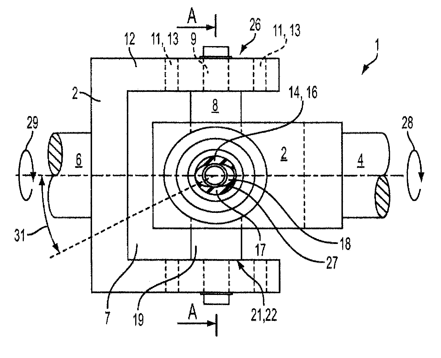
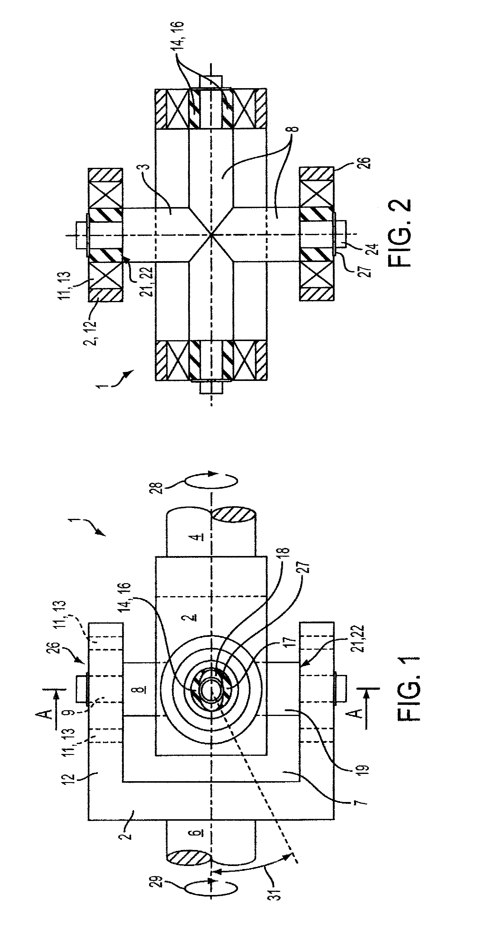
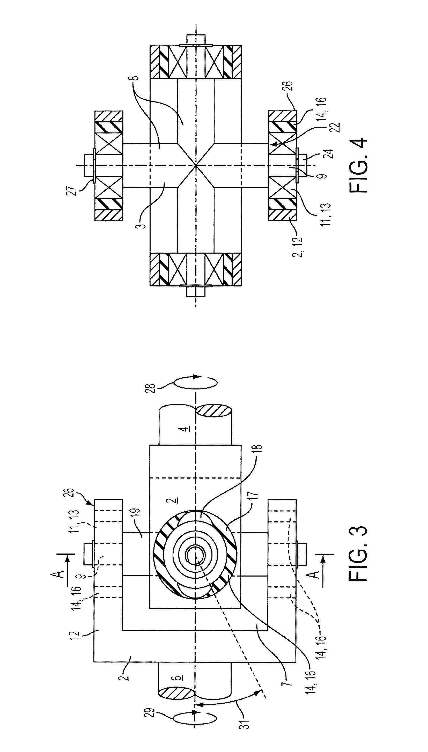
[0035]FIGS. 1 to 4 show a universal joint 1 having two joint yokes 2 and a cross member 3. One of the joint yokes 2 is connected to a driven shaft 4 or drive shaft 4, the other joint yoke 2 being connected to the shaft to be driven 6 or drive shaft 6. The two joint yokes 2 are arranged twisted radially at an angle of 90° in relation to each other so that the two joint yokes 2 form an internal space 7. The cross member 3 is disposed in the internal space 7. The cross member 3 comprises two pin bearers 8 arranged orthogonally in relation to each other. The pin bearers 8 are pivoted in the respectively associated joint yokes 2. The pin bearers 8 crossing each other are rigidly connected with each other. The pin bearers 8 are pivoted, with their pins 9 that are arranged, respectively, at the end sides, in the associated joint yoke 2 or in their yoke arms 12 via bearings 11. The radially opposing bearings 11 of the respective joint yoke 2 each form a pair 13 of bearings. At least one ins...


PUM


Abstract

A universal joint comprises first and second joint yokes having axially opposite yoke arms with bearing bores configured to receive bearings having pin bores, a cross member comprising orthogonally-arranged pin bearers having pins configured to be inserted into the pin bores, and at least one insulation element configured to be inserted between the pins and respective pin bores or the bearings and respective bearing bores, the at least one insulation element having an elliptical cross section that forms crescent-shaped recesses between its inner wall and the pin or bearing that resides therein.

Description

[0001]The present invention is related to: U.S. patent applications Ser. No. 11 / 276,047 entitled “Axial Insulation for a Universal Joint”, U.S. patent application Ser. No. 11 / 276,049 entitled “Axial Insulation for a Universal Cross Joint”, U.S. patent application Ser. No. 11 / 276,052 entitled “Universal Cross Joint with Axial Insulation”, and U.S. patent application Ser. No. 11 / 276,053 entitled “A Cardanic Cross Joint With Insulation”, filed simultaneously herewith.FIELD OF THE INVENTION[0002]The invention relates to a universal joint having two joint yokes and a cross member, wherein one of the joint yokes is connectable or connected with a driven shaft or a drive shaft, and the other joint yoke is connectable or connected to a shaft to be driven or a drive shaft, and wherein the two joint yokes are arranged twisted radially at an angle of 90° in relation to each other so that the two joint yokes form an internal space in which the cross member is disposed.BACKGROUND OF THE INVENTIO...

Claims


Application Information

Patent Timeline
Patent Type & Authority Patents(United States)
IPC IPC(8): F16D3/28
CPCF16C27/066F16D3/28F16C27/06F16D3/40F16D3/41
Inventor GROSS, NORBERTSCHMITZ DR, THOMAS
Owner FORD GLOBAL TECH LLC
Why Eureka
Try Eureka