Tray and recording apparatus

a technology of recording apparatus and tray, which is applied in the directions of thin material handling, printing, transportation and packaging, etc., can solve the problems of difficult stacking of paper sheets supplied as a roll on the discharge tray, and difficulty in paper supply from the rear

Inactive Publication Date: 2008-11-11
SEIKO EPSON CORP
View PDF8 Cites 9 Cited by
  • Summary
  • Abstract
  • Description
  • Claims
  • Application Information

AI Technical Summary

Benefits of technology

[0009]a guide portion, being retractable into or extendable from a medium stacking portion in accordance with the form of the medium to be discharged, and when the medium to be discharged has a predetermined form, being extended from the medium stacking portion so as to guide the medium from a discharge portion to the medium stacking portion. With this arrangement, when the form of a recording medium is such that stacking the medium on the stacking portion is difficult, the recording medium can be guided from the discharge portion to the medium stacking portion. Therefore, the recording medium can be precisely stacked on the medium stacking section.
[0010]When the recording medium is flat, the guide portion is retracted into the medium stacking portion, and when a recording medium is curled in the discharge direction, the guide portion is positioned at the medium stacking portion. With this arrangement, a flat recording medium can be stacked directly on the medium stacking portion, or a curled recording medium can be discharged to the medium stacking portion without being caught between the discharge portion and the medium stacking portion. For the guide portion, a slanted member is included that guides a recording medium from the discharge portion down to the medium stacking portion. With this arrangement, the leading edge of the recording medium can slide along the slanted member, which is shaped like a playground slide, and the leading edge of the recording medium, while sliding along the playground shaped slanted member, can be guided to and smoothly piled on the medium stacking portion.

Problems solved by technology

Since this ink-jet printer handles batches of heavy paper, unlike a small ink-jet printer, it is difficult for paper to be supplied from the rear and discharged at the front, the supply and discharge of paper is performed from the front.
Accordingly, stacking paper sheets supplied as a roll on the discharge tray is difficult.

Method used


Image

  • Tray and recording apparatus
  • Tray and recording apparatus
  • Tray and recording apparatus

Examples


Embodiment Construction

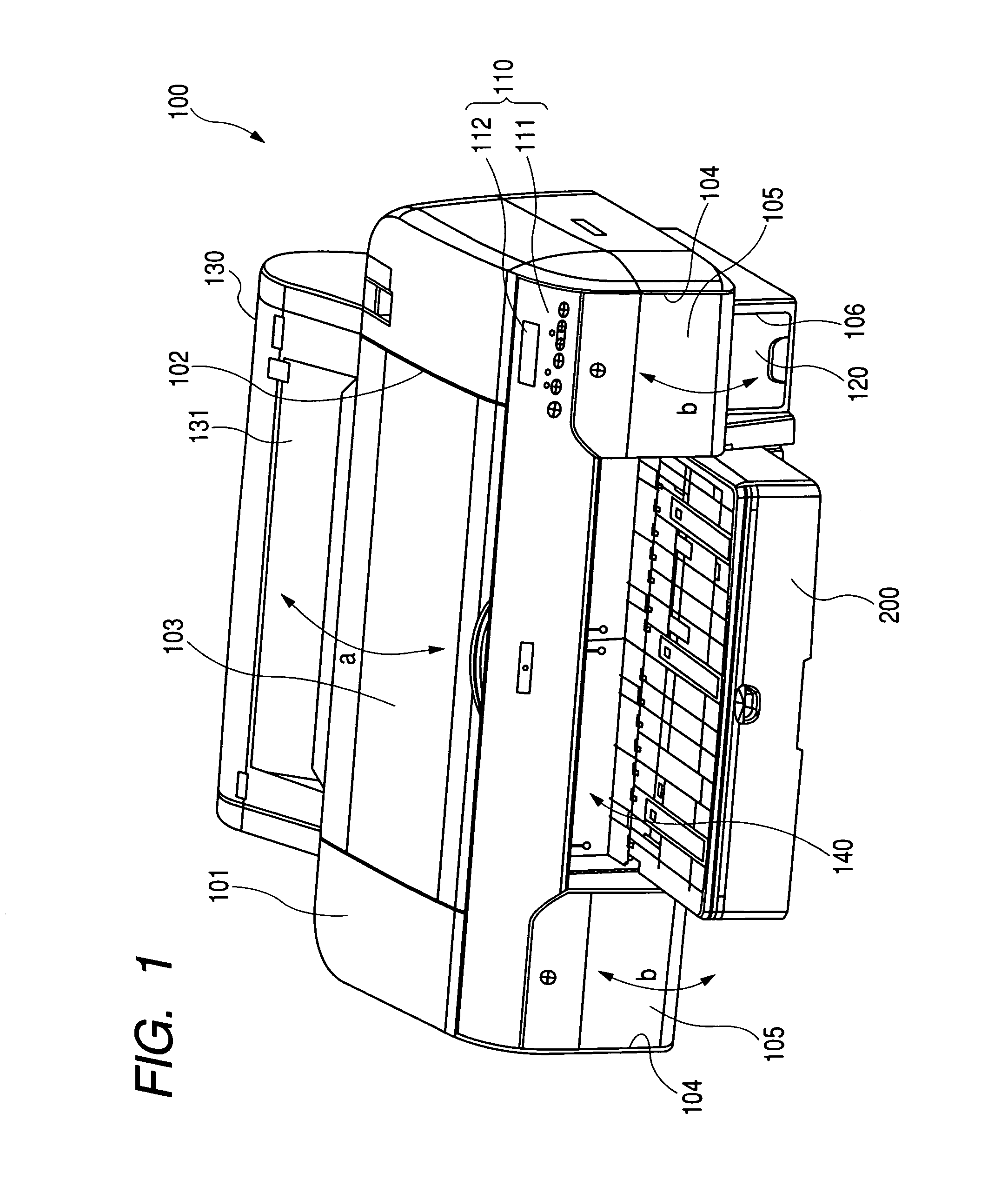
[0028]FIG. 1 is an oblique front perspective view of the overall external appearance of an ink-jet recording apparatus. An ink jet printer 100 is a large desktop printer that can print both cut-sheet paper, ranging in size from, for example, A4 to comparatively large sizes, such as A2, all of which conform to the JIS standards, and paper supplied as a roll. The ink-jet printer 100 is covered by a substantially rectangular parallelepiped cover 101 that, overall, is extended in the widthwise direction.

[0029]A rectangular window 102, formed in the upper face of the housing 101, is covered with a transparent or semi-transparent window cover 103, which is attached so as to be pivotable at a rotary shaft, located at an upper position, and in a direction indicated by a double-headed arrow a in FIG. 1. When the window cover 103 is raised by a user, opening the window 102, maintenance of the internal mechanism can be performed through the window 102.

[0030]Cartridge storage portions 104, wher...


PUM


Abstract

A discharge tray includes a guide portion that is retractable or extendable, relative to medium stacking portions, in consonance with the form of the recording media that are to be discharged. When the recording media that are to be discharged have a predetermined form, the guide portion at the medium stacking portion is prepared so as to guide a recording medium from a discharge portion to the medium stacking portion. With this arrangement, when recording media are so formed that arranging them on the medium stacking portion is difficult, the recording media can be guided from the discharge portion to the medium stacking portion, where they can be stacked accurately.

Description

[0001]The present application is based on Japanese Patent Application No. 2003-126169, the entire contents of which are incorporated herein by reference.BACKGROUND OF THE INVENTION[0002]1. Field of the Invention[0003]The present invention relates to a tray on which recording media, after being discharged, are mounted, a recording apparatus with which this tray is equipped, and a liquid ejection apparatus.[0004]2. Related Art[0005]Of the large recording apparatuses that are presently being marketed, an ink-jet printer is available that can print recording media ranging in size from, for example, A4 to comparatively large sizes, such as A2, all of which conform to the JIS standards. Since this ink-jet printer handles batches of heavy paper, unlike a small ink-jet printer, it is difficult for paper to be supplied from the rear and discharged at the front, the supply and discharge of paper is performed from the front. That is, a paper supply tray and a paper discharge tray are provided ...

Claims


Application Information

Patent Timeline
Patent Type & Authority Patents(United States)
IPC IPC(8): B65H31/00B41J13/10B41J13/00B65H31/20
CPCB41J13/106B65H31/20B65H2402/343B65H2404/691B65H2405/3322B65H2511/10B65H2220/01B65H2220/04B65H2405/11164B65H2402/30
Inventor FUJIOKA, KAZUYUKIMIYAZAKI, KENICHI
Owner SEIKO EPSON CORP
Why Eureka
Try Eureka