Loop antenna for in the ear audio device

a technology of in-ear audio and loop antenna, which is applied in the direction of loop antenna, support/mounting of antenna, electrical equipment, etc., can solve the problems of limited bandwidth of antenna and difficult to overcome, and achieve the effect of reasonable antenna efficiency

Active Publication Date: 2008-11-11
OTICON
View PDF9 Cites 72 Cited by
  • Summary
  • Abstract
  • Description
  • Claims
  • Application Information

AI Technical Summary

Benefits of technology

[0013]Preferably the loop material has a thickness in the direction perpendicular to the loop axis of about 0.01 to 0.15 mm. These dimensions allow the loop to be made with a variety of different processes, and at the same time the requirement for the size of the loop in order to gain sufficient cross sectional material is not excessive.
[0015]Preferably the loop area is as large as possible and no less than 45 mm2. This allows a reasonable antenna efficiency.

Problems solved by technology

The prior art antenna has limited bandwidth, a problem, which is hard to overcome given the space limitations of an ITE hearing aid.

Method used


Image

  • Loop antenna for in the ear audio device
  • Loop antenna for in the ear audio device
  • Loop antenna for in the ear audio device

Examples


Embodiment Construction

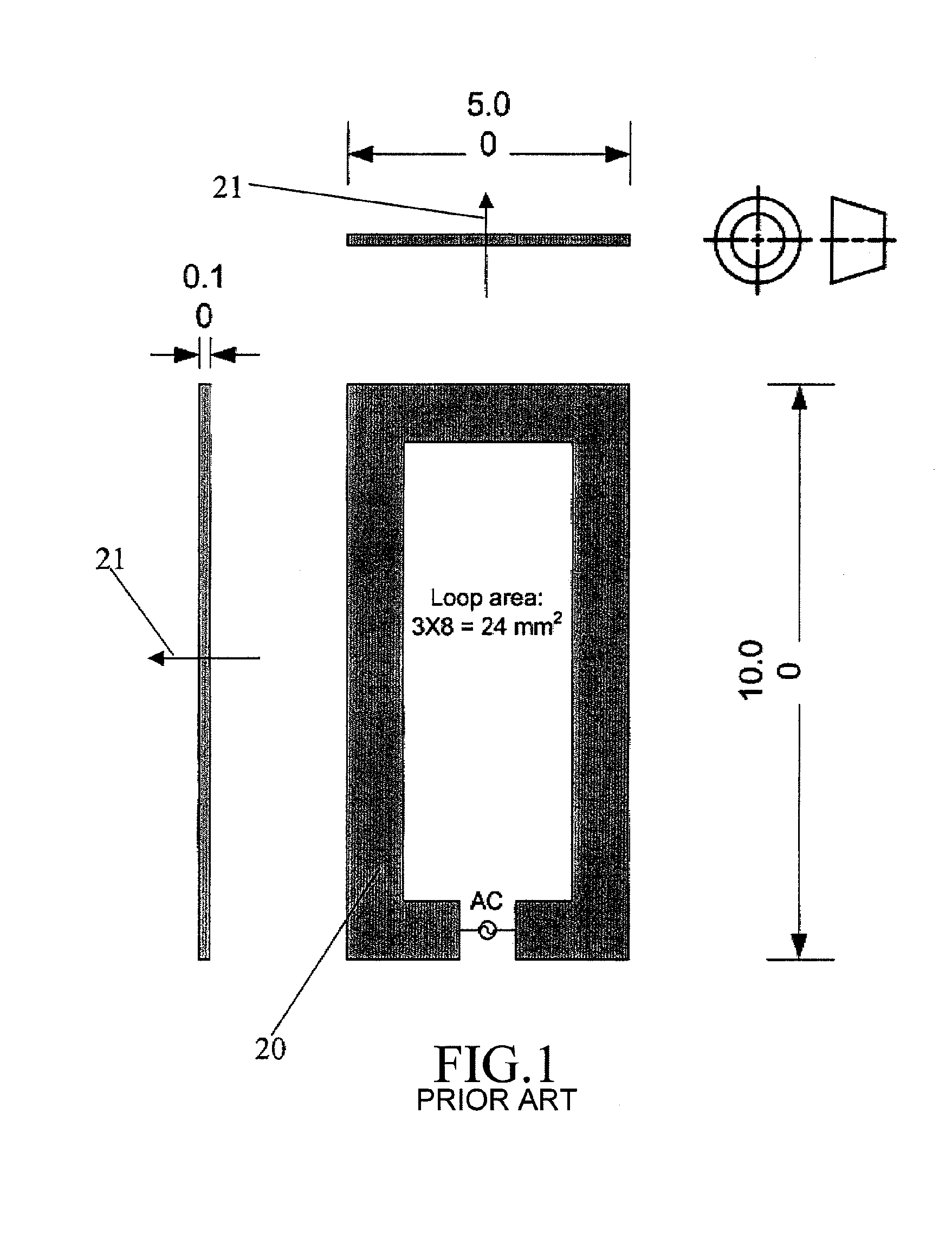
[0019]FIG. 1 shows a prior art antenna where a square loop 20 with an open area compatible with the size of a battery drawer of an ITE or CIC hearing aid is arranged with the loop material extending in the plane of the outer surface of the battery drawer and orthogonally to the loop axis. This loop will have a loop area of 24 mm2. The loop axis is defined by arrow 21. The thickness of the loop material is 0.1 mm in the direction of the loop axis 21. The loop material extends primarily perpendicular to the loop axis 21. The product A, of the extension of the loop material in the direction of the loop axis 21 and the extension of the loop material perpendicular to the loop axis 21 is inversely proportional with the reactive part of the antenna impedance, and this part of the impedance should not be increased. The size of the product A should thus preferably not be any smaller when changes in the loop antenna are made.

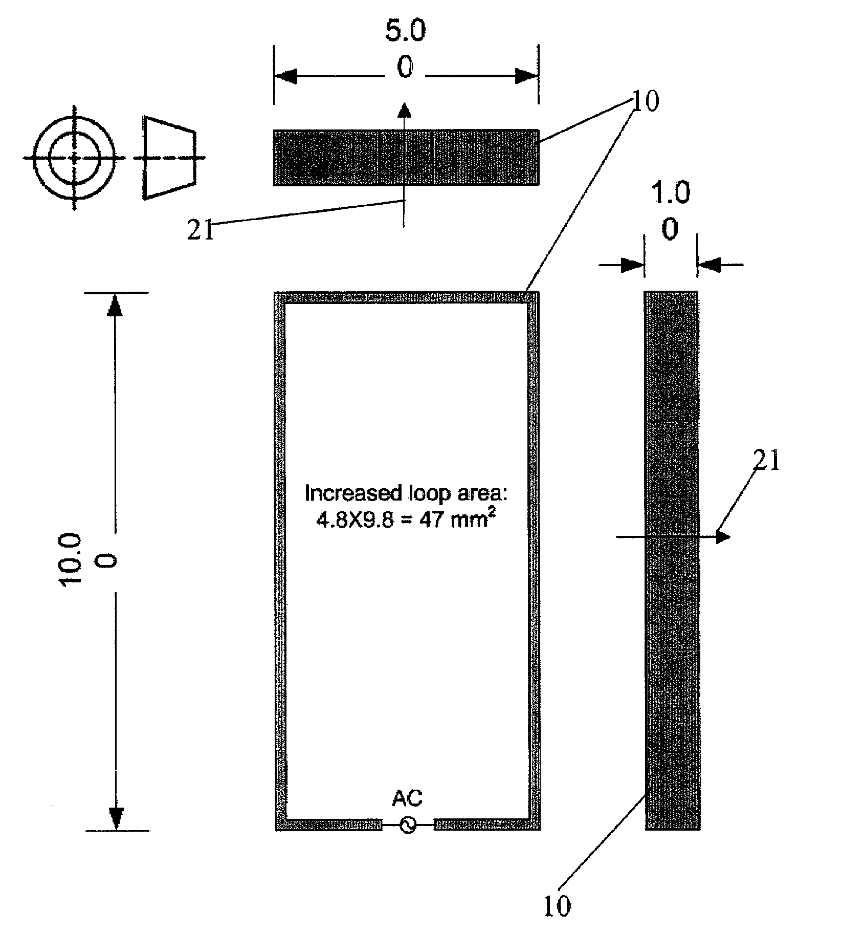
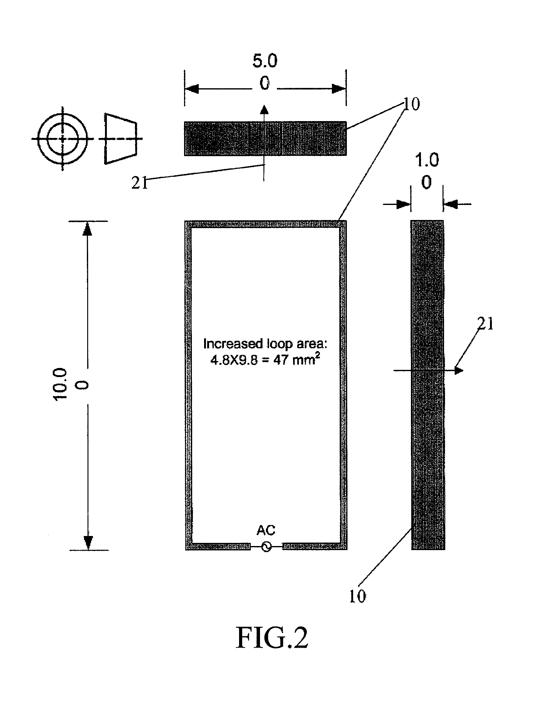
[0020]In FIG. 2 the improvement achieved by the invention is visible...


PUM


Abstract

The invention regards a communication device which is adapted for placement in a users ear and comprises a shell part enclosing an input transducer for receiving an input signal, a signal processing device and an output transducer for providing a signal perceivable as sound, a battery located at a surface part of the shell which is facing away from the head of the user, a transmission and reception circuit for transmission and / or reception of electromagnetic energy, and where an antenna for radiating and / or receiving electromagnetic energy is arranged with a first surface turned towards the surroundings and a second surface located in close proximity of the battery whereby the antenna forms a loop with a loop axis pointing away from the ear and head, whereby the loop material has a wider extension in the direction of the loop axis than in the direction perpendicular to the loop axis.

Description

AREA OF THE INVENTION[0001]The invention regards a loop aerial or antenna for an in the ear audio device. There are two measures which have major impact on the efficiency and bandwidth of loop antennas. These measures are the area surrounded by the loop and the cross section of the conductor forming the loop. The area determines the efficiency and the cross section determines the reactive part and bandwidth of the antenna impedance.BACKGROUND OF THE INVENTION[0002]It is common knowledge that electrically small antennas exhibit high quality factors and small bandwidths i.e. the bandwidth follows size. In prior art publication WO 2005081583 A1 a small loop antenna is disclosed wherein the antenna is made of a conducting strip lying in the same plane as the outer surface of the battery drawer of a hearing aid. The prior art antenna has limited bandwidth, a problem, which is hard to overcome given the space limitations of an ITE hearing aid.[0003]The present invention provides means to ...

Claims


Application Information

Patent Timeline
Patent Type & Authority Patents(United States)
IPC IPC(8): H01Q7/00
CPCH01Q1/273H01Q7/00H04R25/554H04R2225/51H04R2420/07
Inventor KNUDSEN, OVECHRISTENSEN, KARE TAIS
Owner OTICON
Why Eureka
Try Eureka