Foam dispenser

a foam dispenser and dispenser technology, applied in the field of foam dispensers, can solve the problems of high cost, complex technology, and need for pump assembly

Active Publication Date: 2012-12-25
REXAM AIRSPRAY
View PDF31 Cites 9 Cited by
  • Summary
  • Abstract
  • Description
  • Claims
  • Application Information

AI Technical Summary

Benefits of technology

[0012]Thus, there is no longer the need to provide a separate pump for pumping a colorant liquid in order to form such stripe. In other embodiments the dispensate material may contain flavoring materials or scent materials to give the foam flow a desired taste or scent. This may also be done in combination with each other or in combination with a coloring material. Any other dispensate material having certain desirable characteristics may also be used as dispensate material in the present invention.
[0013]In an embodiment the contact surface of the porous matrix is arranged at a top or sides of the dispensing channel. After that an amount of foam has been dispensed with the foam dispenser the dispensing channel will be filled with foam. This foam will after a certain time return to a fluid state and therewith the volume of the foam material will substantially decrease. By placing the porous matrix at the top or side of the dispensing channel, the contact surface will no longer be in contact with the foam or liquid as soon as the foam is at least partially returned to the liquid state, and the dispensate material will no longer be released from the porous matrix to the liquid remaining in the dispensing channel. Thus even when the foam dispenser is not used for a certain time there will still be enough dispensate material to provide a stripe on foam being dispensed from the foam dispenser. Furthermore, it is prevented that a relatively large amount of dispensate material is released in the foam / liquid residing in the dispensing channel. This foam when dispensed during renewed actuation of the foam dispenser would have a stripe which is too wide or has a too dark color, or in the case of flavoring or scenting dispensate materials, a too strong taste or smell.
[0015]In contrast to the above it is remarked that, in the case of a liquid dispenser, the liquid which will be present in the dispensing channel after dispensing, will keep occupying the whole dispensing channel since no volume change in the liquid will occur. As a consequence, dispensate material may continuously be released in the liquid being in contact with the contact surface of the porous matrix. As a possible result, all dispensate material will be used before the liquid in the liquid reservoir is depleted, and therefore not all liquid dispensed by the liquid dispenser would have the desired effect of dispensate material in the dispensed liquid. When in a foam dispenser the contact surface of the porous matrix is not placed at the bottom of the dispensing channel, this risk on early depletion of the dispensate material is substantially reduced.

Problems solved by technology

A drawback of this known foam dispenser is that a separate pump assembly has to be provided to form a second liquid or foam flow which is used to provide a stripe in the main foam flow.
This makes the foam dispenser technically complex and more expensive.

Method used


Image

  • Foam dispenser
  • Foam dispenser
  • Foam dispenser

Examples


Embodiment Construction

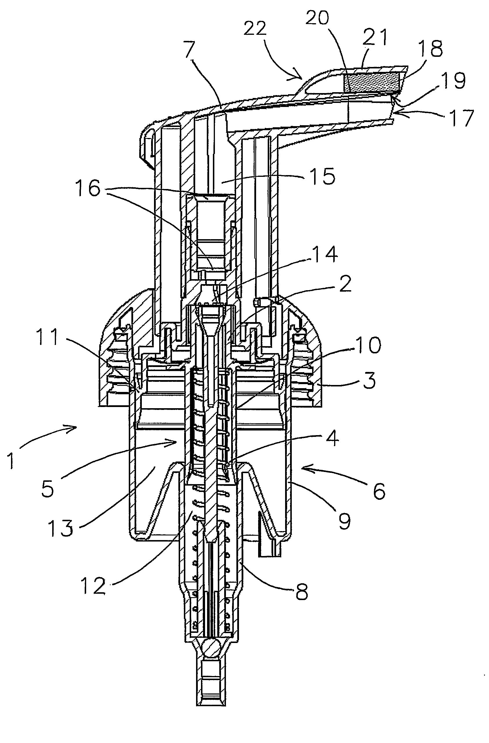
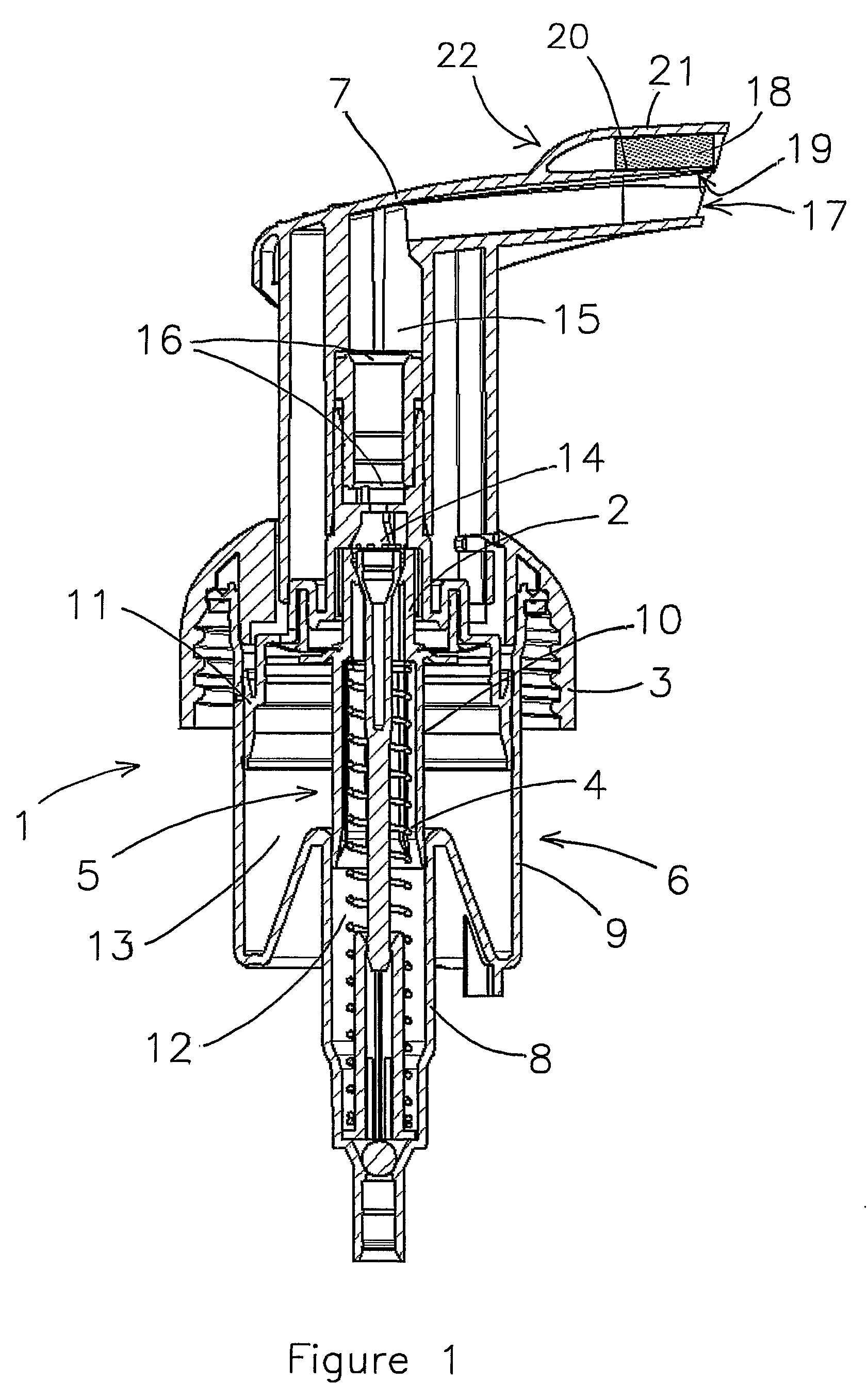
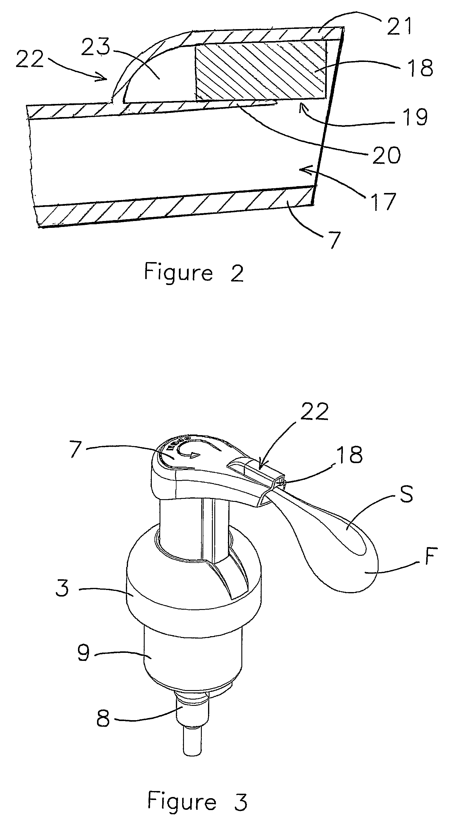
[0026]FIG. 1 shows a foam dispenser for dispensing a foam, which foam dispenser is indicated by reference numeral 1. The foam dispenser 1 comprises a pump assembly 2 which is fixed by means of a fixing collar 3 on a reservoir (not shown) in which the liquid to be dispensed is stored. The pump assembly 2 comprises a liquid pump 5, an air pump 6 and a common actuation part 7. The liquid pump 5 and the air pump 6 are piston pumps. The pump housing of both the liquid pump 5 and the air pump 6 is formed by a double cylinder, comprising liquid pump cylinder 8 and air pump cylinder 9. In the liquid pump cylinder 8 a liquid piston 10 and in the air pump cylinder 9 an air piston 11 is fitted, respectively.

[0027]The liquid pump cylinder 8 and the liquid piston 10 delimit a liquid pump chamber 12. The air pump cylinder 9 and the air piston 11 delimit an air pump chamber 13.

[0028]The basic principle of operation of the foam dispenser 1 will now be explained. Upon actuation of the common actuati...


PUM


Abstract

A foam dispenser having a pump assembly includes a liquid pump, an air pump and a common actuation part to simultaneously actuate the liquid pump and the air pump. The pump assembly includes a dispensing channel having a dispensing opening. The pump assembly further includes a porous matrix which contains a dispensate material. A contact surface of the porous matrix is arranged in communication with the dispensing channel, so that foam being formed in the pump assembly and dispensed through the dispensing channel comes into contact with the contact surface to introduce dispensate material released from the porous matrix in the foam.

Description

CROSS-REFERENCE TO RELATED APPLICATIONS[0001]This application is the National Stage of International Application No. PCT / NL2006 / 000351, filed Jul. 11, 2006, the contents of which is incorporated by reference herein.FIELD OF THE INVENTION[0002]The present invention relates to a foam dispenser for dispensing a liquid in the form of a foam. More particularly, the present invention relates to a foam dispenser with which a foam flow can be dispensed which comprises a stripe which may have another color than the main foam flow.BACKGROUND OF THE INVENTION[0003]Manual foam dispenser are well known in the art and for instance disclosed in EP 0613728 B1. These foam dispensers comprise a pump assembly which can be mounted on or in an opening of a reservoir for holding a liquid to be dispensed in the form of a foam. The pump assembly comprises a liquid pump for pumping the liquid from the reservoir and an air pump to mix air with the liquid in order to form a foam. The foam is dispensed through...

Claims


Application Information

Patent Timeline
Patent Type & Authority Patents(United States)
IPC IPC(8): B67D7/78B67D7/76B67D7/70
CPCB05B11/0078B05B11/3087B05B11/3001B05B11/1001B05B11/1087
Inventor VAN DER HEIJDEN, EDGAR IVO MARIA
Owner REXAM AIRSPRAY
Why Eureka
Try Eureka