
Method for hydroenhancing fabrics using a shaped orifice

a technology of hydro-enhancing fabrics and orifices, which is applied in the direction of drying machines, lighting and heating apparatus, and drying machines with progressive movements. it is not feasible to simply increase the number of orifices per inch, and is difficult to make and maintain multiples

Inactive Publication Date: 2003-06-05
TEXTILE ENHANCEMENTS INT
View PDF12 Cites 10 Cited by
  • Summary
  • Abstract
  • Description
  • Claims
  • Application Information

AI Technical Summary

Benefits of technology

[0008] It is not feasible to simply increase the number of orifices per inch in order to deliver more energy per pass. The material that comprises an orifice strip must be of sufficient thickness to withstand the liquid pressure behind it. This thickness is usually about ten time greater than the diameter of a typical circular orifice, e.g. an orifice strip having 0.003 inch diameter (or wide) orifices can be from about 0.010 up to 0.040 inch thick. If the orifice passage was a constant 0.003 inch diameter (or width) for the full 0.040 inch of its length, the resulting stream would become divergent, i.e. would not be coherent or columnar. In order to produce coherent or columnar jet that retains its effectiveness over greater distances, an orifice passage can be relieved at the exit end. This construction reduces the effective length of the orifice passage and results in a coherent or columnar jet. A negative side effect of this construction is to create a minimum distance between adjacent orifices, in order to retain adequate material in, and strength of, the orifice strip.
[0011] In the fabric support configurations that involve a foraminous support, the references also disclose the use of a vacuum to enhance the hydroenhancement process. The vacuum keeps the water from pooling or flooding, and thereby impeding the ability of the water jets to impinge the fabric. The vacuum can also facilitate the handling of the fabric by holding it tight to the support or support / transport member.
[0016] The present invention contemplates hydroenhancing fabrics with a liquid exiting a pressurized manifold through an array of elongated orifices. The liquid jet emanating from each elongated orifice is columnar or coherent in form, i.e. its cross section has minimum variation from where the liquid jet exits the orifice to where the liquid jet impinges the fabric. The benefits of using elongated orifices are several: to permit the presence of solid impurities in the pressurized liquid that would clog an array of circular orifices; to improve the energy efficiency of the hydroenhancement process; to reduce the number of passes required to create the desired hydroenhancement effect; to simplify the "striping" of fabrics, i.e. making a consistent pattern of alternating lighter and darker lines across the width of the fabric web with a single manifold and orifice strip; to permit hydroenhancing of high-warp-count fabrics without undesirable patterning; and to simplify the machinery that would be required to accomplish any given degree of hydroenhancement.
[0018] The distinguishing characteristic of the present invention over the prior art is the use of elongated orifices. One elongated orifice that is 0.003 inch wide and 0.030 inch long can deliver approximately ten times as much energy as a circular orifice of 0.003 inch diameter. This property permits the development of hydroenhancing machines with fewer manifolds and orifice strips, resulting in less expensive equipment, and / or quicker processing times for the hydroenhancement of a fabric.

Problems solved by technology

This technology is useful for hydro-entanglement, i.e. the process of making a fabric from a loose bat of non-interwoven loose fibers, but the energy available at the maximum pressure is not adequate to appreciably alter the appearance or properties of a pre-existing fabric.
The method disclosed in U.S. Pat. No. 5,737,813 to Sternlieb could be used to create a stripe pattern, but because the energy delivered by a single circular orifice is insufficient to provide adequate wash-out, the striping effect must be produced either with a series of orifices in multiple manifolds, or by making multiple passes through one machine.
It is not feasible to simply increase the number of orifices per inch in order to deliver more energy per pass.
It is difficult to make and maintain multiple orifice / manifolds alignment so that successive impingements fall on the same wash-out line; with the result that the striping becomes blurred.
The vacuum keeps the water from pooling or flooding, and thereby impeding the ability of the water jets to impinge the fabric.
However, nothing in the references shows or suggests an elongated orifice shape, or an orifice other than a circle.

Method used


Image

  • Method for hydroenhancing fabrics using a shaped orifice
  • Method for hydroenhancing fabrics using a shaped orifice
  • Method for hydroenhancing fabrics using a shaped orifice

Examples


Embodiment Construction

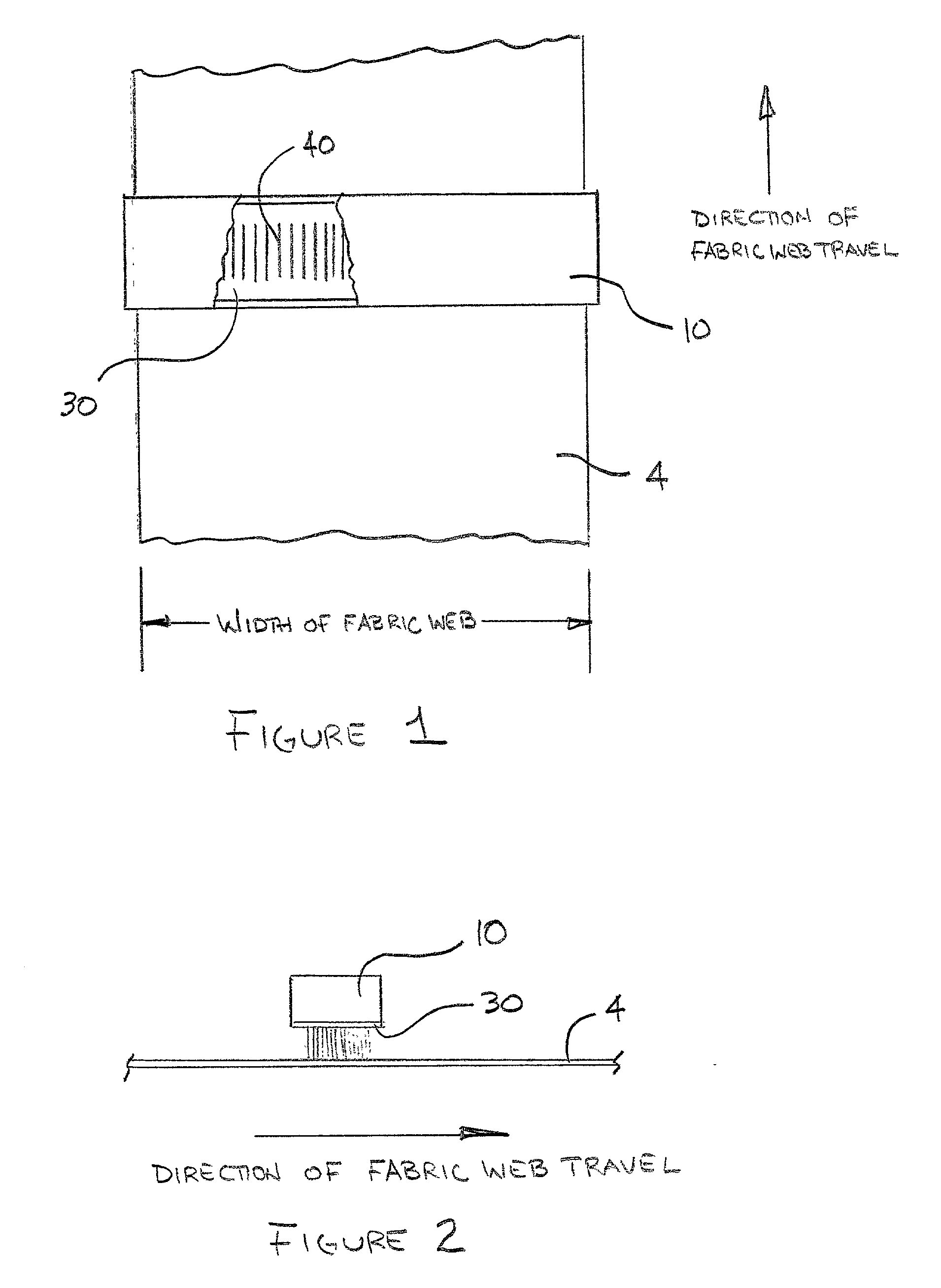
[0105] FIG. 1 is a plan view of a moving web and a partially cut-away manifold.

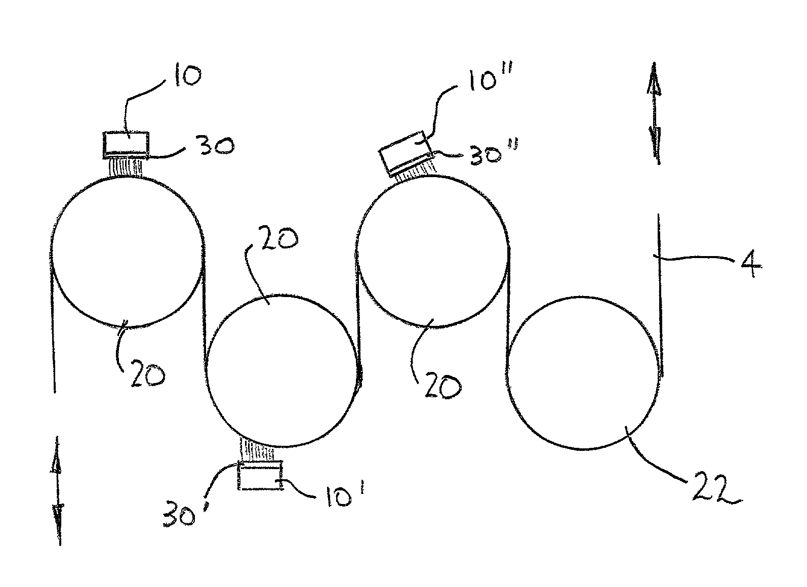
[0106] In one embodiment of the present invention, a fabric web 4 passes underneath a manifold 10. Partially shown in the cut-away portion of manifold 10 is the orifice strip 30 and a series of parallel elongated orifices 40 in the orifice strip 30, where the major axes of the elongated orifices 40 are parallel with the direction of travel of fabric web 4. In FIG. 1, manifold 10 is placed so its longitudinal axis is perpendicular to the direction of travel of fabric web 4, and fabric web 4 appears to be on a flat support surface (not shown). However, it is within the practice of the present invention to orient manifold 10 so that its longitudinal axis is not perpendicular to the direction of travel of fabric web 4.

[0107] FIG. 2 is a side elevation view of a moving web, a manifold and an orifice strip.

[0108] In one embodiment of the present invention, moving fabric web 4 passes underneath manifold 10 and o...


PUM

PropertyMeasurementUnit
angleaaaaaaaaaa
diameteraaaaaaaaaa
diameteraaaaaaaaaa

Abstract

A method for hydroenhancing fabrics is described. The method uses the force of pressurized liquid passing through elongated orifices and impinging on the fabric. The pressurized liquid exits in a coherent or columnar fashion from elongated orifices that are generally rectangular or linear in shape. The elongated orifices can be arranged so as to produce various effects on a web of fabric, including striping, graduated shading and seer-suckering. The elongated orifices also facilitate the hydroenhancement of high-warp-count fabrics without streak or moire effects. Liquid filtration can be relaxed without clogging the orifices, because the elongated orifices permit larger solid objects to pass. The use of elongated orifices also enhances the energy efficiency of the hydroenhancement process.

Description

BACKGROUND OF THE PRESENT INVENTIONSUMMARY OF THE PRIOR ART[0001] This invention relates to a method for hydroenhancing fabrics, and more particularly to a method for hydroenhancing fabrics using a shaped orifice wherein a liquid under pressure is forced through a non-circular orifice in a coherent jet and impinges onto a fabric. Multiple orifices are typically used, and the shape and orientation of the orifices (e.g. the distance between adjacent orifices, the angle between the major axes of the orifices and the direction of fabric travel and the direction of impingement) can be modified to effect different hydroenhancement properties. The method of hydroenhancement can be practiced using a variety of machinery configurations. One use for the method of the present invention is to impart "striping," i.e. a selective color wash-out to produce a pattern of alternating lighter and darker stripes across the width, and running the length of a fabric web.[0002] The impingement of a liquid...

Claims


Application Information

Patent Timeline
Patent Type & Authority Applications(United States)
IPC IPC(8): D04H1/46D04H18/04
CPCD04H18/04D04H1/465Y10T442/689
Inventor STERNLIEB, HERSCHELZOLIN, PAUL F.
Owner TEXTILE ENHANCEMENTS INT
Learn More