Device for removing objects from enclosed areas

a technology for removing objects and enclosed areas, which is applied in the direction of hollow article cleaning, mechanical equipment, hair combs, etc., can solve the problems of sewage system failure, back-up, sewage system shutdown, etc., and achieve the effect of minimizing risks, sufficient diameter, length and material

Inactive Publication Date: 2000-05-09
DML
View PDF12 Cites 10 Cited by
  • Summary
  • Abstract
  • Description
  • Claims
  • Application Information

AI Technical Summary

Benefits of technology

The invention employs a cutting means comprising a cutting member for cutting objects that may obstruct the flow of fluid in a pipe. In the preferred embodiment of the invention, the cutting member preferably has two semi-rigid cutting arms. More particularly, each of two cutting arms are preferably comprised of a cable which, when moved at an appropriate speed, is of a sufficient diameter, length, and material to be advantageously semi-rigid; namely, the cutting arms are rigid enough to cut undesirable plant roots and yet flexible enough to flex, fray or otherwise move around fixed obstructions, such as offset joints or protruding tap-ins, to minimize the risks of damaging the fixed obstruction, the interior pipe wall, and the cutting arms.

Problems solved by technology

Many problems stem from the growth of roots in underground sanitary and storm sewers.
For example, if plant roots are left untreated, they can cause line blockages, back-ups, and sewage system failure.
Ultimately, such root growth typically causes shutdown of the sewer.
The removal of plant roots from sewage lines poses several problems.
Various methods that have been employed to remove such roots have hertofore proven unsatisfactory.
However, the use of such rigid saws poses several problems.
In particular, due to the precision required and the risk of damage to the inside wall of a pipeline, operators of rigid saws are often unable or unwilling to use a large enough saw blade inside the sewage line which is necessary to fully cut the root.
When that problem is coupled with the circumstances typically existing in sewage lines, such as the presence of offset joints or protruding tap-ins typically encountered in the field, often an undersized blade will be used.
An undersized blade while minimizing these problems only partially removes root blockage.
Such partial removal reduces the pipeline's effective inside diameter in comparison to its original, unobstructed diameter.
Consequently, the hydraulic pump-motor system experiences reduced flow capacity and increased loading.
Moreover, even an undersized rigid saw blade can get jammed in the sewer line which could damage the sewer cleaning equipment and require that the underground sewer line and the hydraulic motor be excavated and repaired or even replaced.
However, that method tends to have a hammering effect on the inside surface of a pipeline which could cause excessive wear or damage to the sewage line.
Spring-loaded blades are disadvantageous since they cannot effectively operate in the upstream direction of the pipeline.
In particular, due to the conical orientation of the rotating blades, if the cutter were operated in an upstream, concave direction, it would likely become stuck in the line once it encounters a root or other obstruction.
In addition, if the hydraulic motor and associated cleaning equipment is initially on the downstream end of the pipeline, the operator of the cleaning equipment is inconvenienced because the cleaning equipment must be moved upward to the upstream side of the pipeline before cleaning the line.

Method used


Image

  • Device for removing objects from enclosed areas
  • Device for removing objects from enclosed areas
  • Device for removing objects from enclosed areas

Examples


Embodiment Construction

While the particular embodiment of the invention illustrated in FIGS. 1 through 4 can be applied to a particular object, it will be recognized by those skilled in the art that by making alterations to the dimensions, shapes and features of aspects of this invention, the invention is useful for other objects or applications.

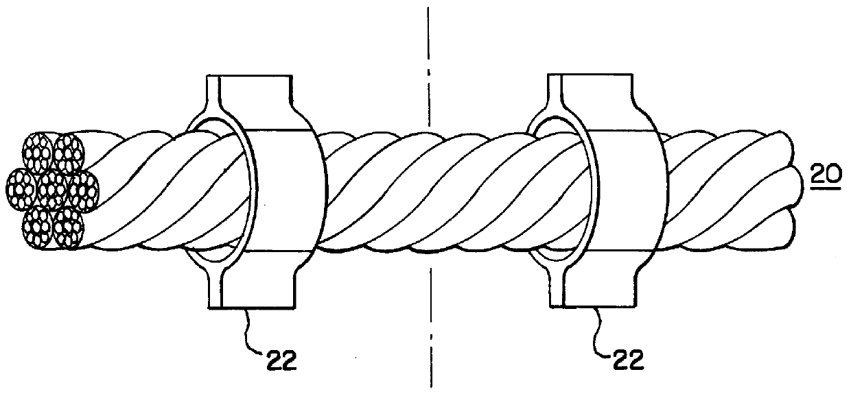
The invention discloses a device for cleaning objects from enclosed areas which includes a cutting member (5) having at least one rotatable semi-rigid cutting arm (20) and an attachment member (10) for attaching the cutting arm (20) to the cutting member (5).

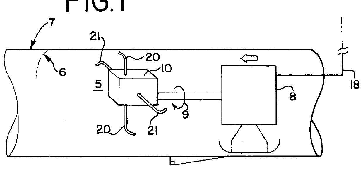
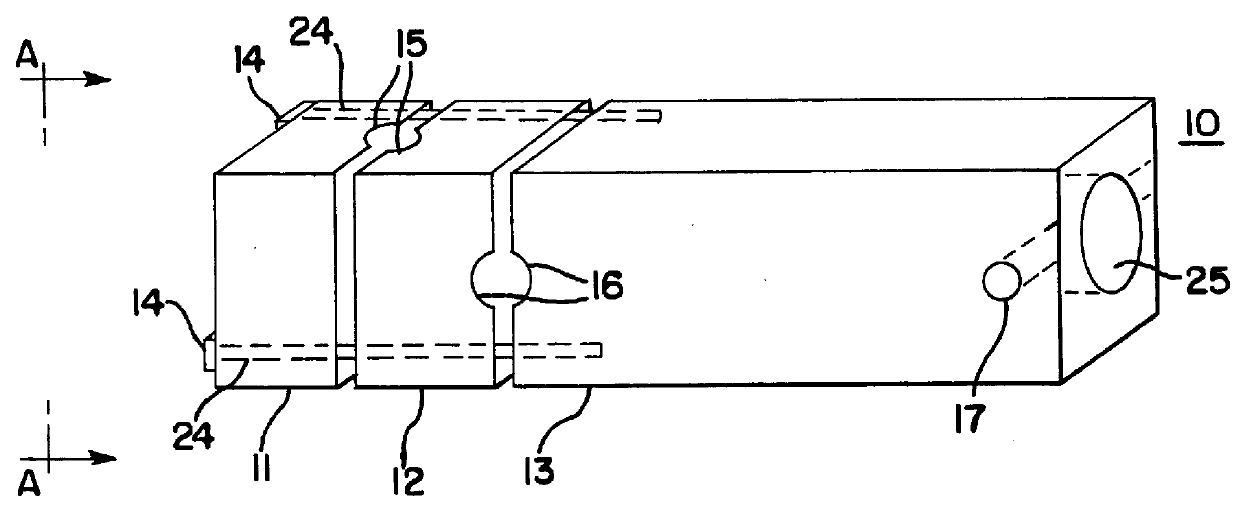
FIG. 1 shows a schematic of the preferred embodiment of the invention. As shown in FIG. 1, an attachment member (10) is attachable to a motor shaft (9) which is connected to a motor (8). The attachment member (10) preferably has attached thereto two cutting arms; namely a first cutting arm (20) and a second cutting arm (21). First and second cutting arms (20) and (21) each preferably extend out of attachment m...


PUM


Abstract

A device for removing objects from a contained area or pipeline. A cutting means comprising at least one rotating, semi-rigid cutting arm of sufficient diameter, length, and material such that it is rigid enough to cut an object while having sufficient flexibility to avoid damaging an interior wall of said pipeline and to increase cutting area during operation. The cutting member, attachable to a shaft which is rotated by a standard motor, rotates concentrically with a longitudinal axis of the pipeline causing the semi-rigid cutting arm to move and flex during operation. The device may be employed inside a pipeline in both axial directions toward either end of said pipeline.

Description

This invention relates to removing objects from enclosed areas and more particularly to a rotary cutting tool for removing plant roots from sewage lines.Many problems stem from the growth of roots in underground sanitary and storm sewers. For example, if plant roots are left untreated, they can cause line blockages, back-ups, and sewage system failure. Ultimately, such root growth typically causes shutdown of the sewer. It is therefore necessary to partially or totally remove roots from sewage lines.The removal of plant roots from sewage lines poses several problems. In particular, when de-rooting a sewer, care must be taken to avoid damaging the above-ground foliage which is typically on private land and planted and cared for by a homeowner. Although the above-ground foliage may be delicate, it is important to eliminate as much of the root as possible to minimize its regrowth. If a root is not completely removed, as when one branch of a root is cut near its top, multiple roots may ...

Claims


Application Information

Patent Timeline
Patent Type & Authority Patents(United States)
IPC IPC(8): B08B9/02B08B9/04E03F9/00B08B9/051
CPCE03F9/005B08B9/051
Inventor FOSTER, LARRY
Owner DML
Why Eureka
Try Eureka