
Systems and methods used to reserve a constant battery capacity

a battery capacity and system technology, applied in secondary cells, cell components, therapy, etc., can solve the problems of battery power depletion below, device itself becoming nonfunctional, and various system settings may be lost, so as to reduce the quantity or quality, reserving battery capacity

Active Publication Date: 2008-11-11
ADVANCED NEUROMODULATION SYST INC
View PDF6 Cites 521 Cited by
  • Summary
  • Abstract
  • Description
  • Claims
  • Application Information

AI Technical Summary

Benefits of technology

The present invention provides a system and method for maintaining a constant battery reserve capacity for therapeutic devices. This is achieved by controlling the battery's reserve capacity to match the device's predetermined reserve capacity, which is the amount of battery capacity needed for the device to operate after its normal operational battery capacity has been exhausted. The invention takes into account various factors such as battery output voltage, output current, recharge rate, discharge rate, battery age, battery temperature, and programmed activation thresholds. The invention can be used in implantable electronic stimulation systems and other therapeutic devices that use rechargeable batteries.

Problems solved by technology

Many battery-powered therapeutic devices, such as electronic stimulation systems, typically cannot have battery power depleted below a certain percentage of total capacity before the device's processor and the device itself become nonfunctional.
Also, for devices employing memory and / or processors, if power is completely drained from the battery power source, various system settings may be lost if minimum operational power is not maintained.
The foregoing fixed voltage-level method is inefficient because it reserves energy in excess of minimum operational power that cannot be used for a device's function during normal operating periods.

Method used


Image

  • Systems and methods used to reserve a constant battery capacity
  • Systems and methods used to reserve a constant battery capacity
  • Systems and methods used to reserve a constant battery capacity

Examples


Embodiment Construction

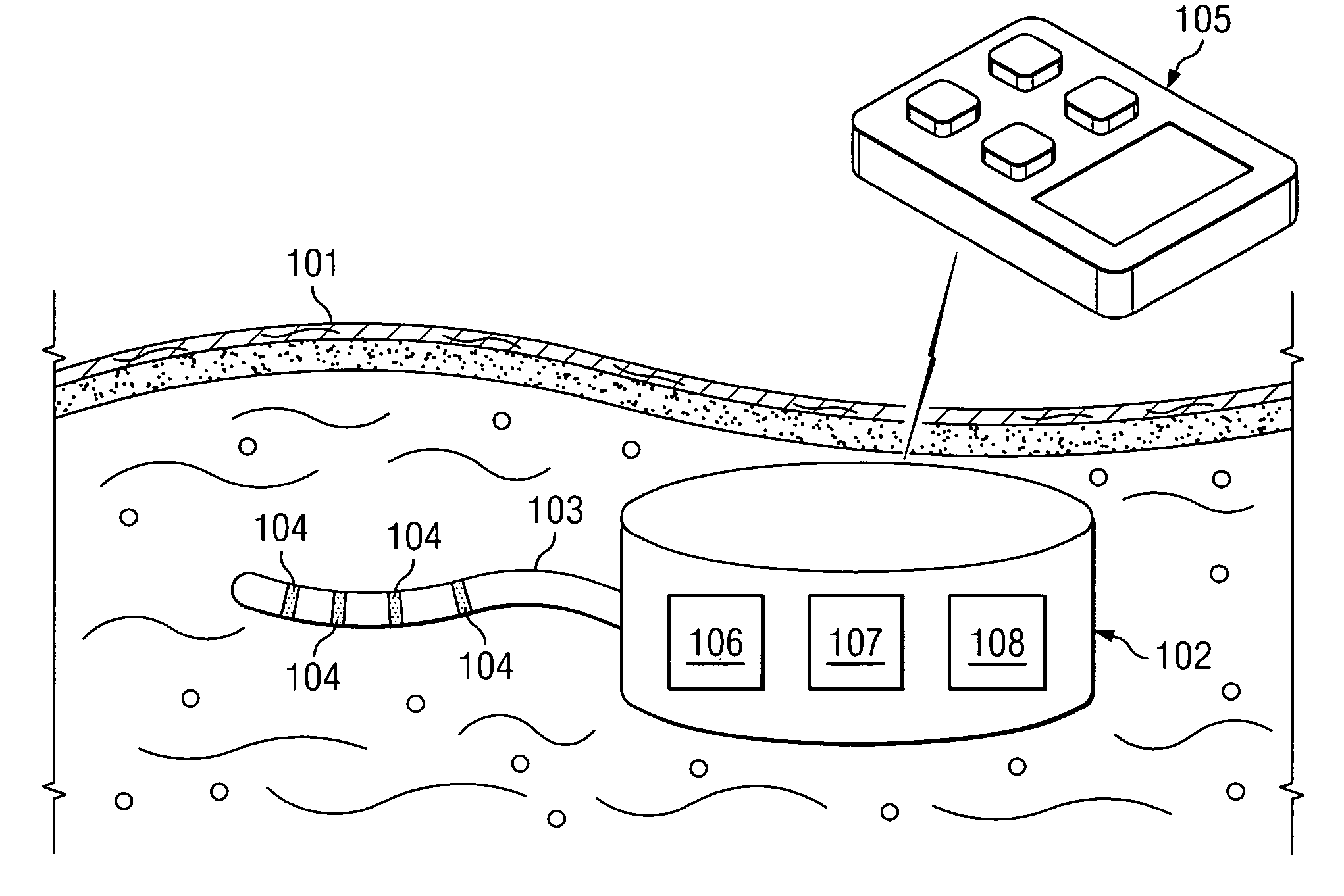
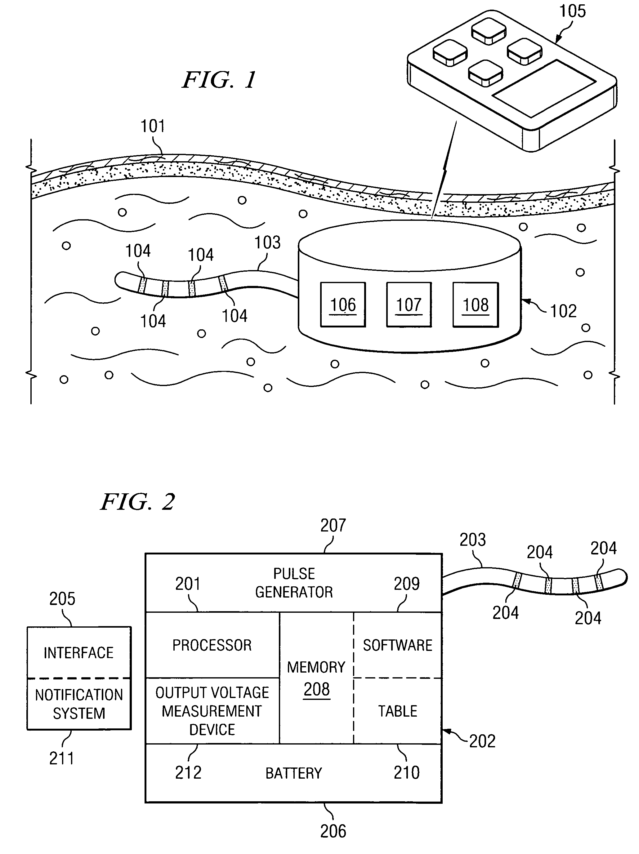
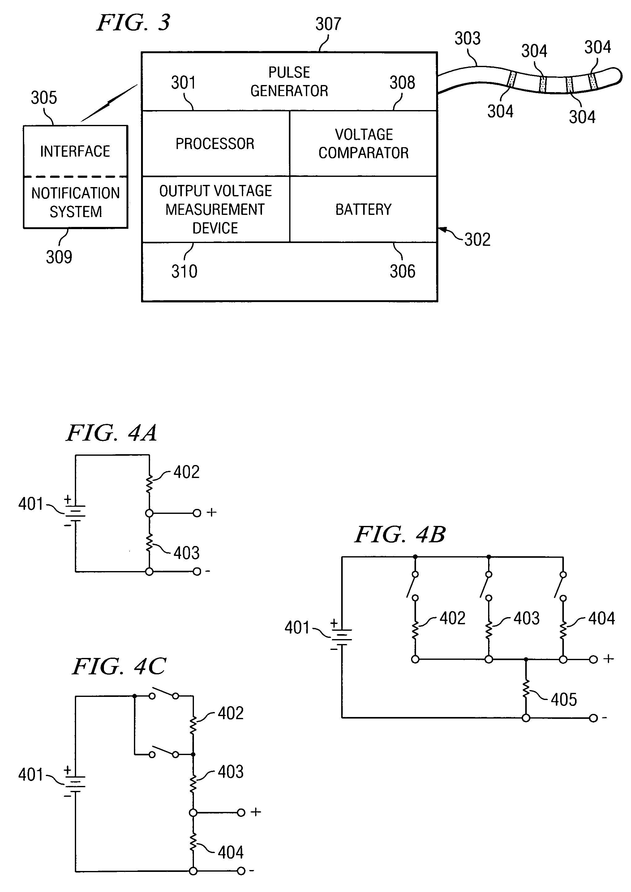
[0027]FIG. 1 shows an electronic stimulation system adapted according to a preferred embodiment of the present invention. As shown in FIG. 1, an exemplary electronic stimulation system includes a pulse generating portion, shown here within pulse generator housing 102, and a stimulation delivery portion, shown here including electrodes 104. In the illustrated embodiment, pulse generator housing 102 may be implantable and inserted surgically beneath the skin 101 of a patient. Electrodes 104 may be coupled to a pulse generator 107 located inside implantable pulse generator housing 102 via lead 103. Electrodes 104 are located in an area selected to receive electrical stimulation. In some embodiments, more or less electrodes 104 and / or leads 103 than shown may be used. Electrodes 104 and portions of lead 103 in the illustrated embodiment are electrically conductive and capable of delivering an electrical pulse to the selected area.

[0028]Embodiments configured other than illustrated in FI...


PUM


Abstract

Techniques are disclosed which provide a substantially constant battery reserve capacity with respect to therapeutic medical devices. Accordingly, a battery control system may be operable to maintain a substantially constant reserve capacity throughout the life of the battery. The battery reserve capacity activation threshold may be set and continuously or periodically updated so that a battery's remaining capacity equals the predetermined reserve capacity when the measured parameter reaches the activation threshold, thereby allowing a maximum amount of a battery's total capacity to be employed for therapeutic use and reserve only that portion of that capacity determined to provide for a desired level and / or period of device function after reaching the reserve threshold.

Description

CROSS-REFERENCE TO RELATED APPLICATIONS[0001]The present application claims priority to U.S. Provisional Patent Application Ser. No. 60 / 575,466, entitled “SYSTEMS AND METHODS USED TO RESERVE A CONSTANT BATTERY CAPACITY,” filed May 28, 2004, the disclosure of which is hereby incorporated herein by reference. The present application is related to commonly assigned U.S. Provisional Patent Application Ser. No. 60 / 568,384 entitled “MULTI-PROGRAMMABLE TRIAL STIMULATOR,” filed May 5, 2004, the disclosure of which is incorporated herein by reference.TECHNICAL FIELD[0002]The present invention relates generally to systems relying upon battery power, and more particularly to systems and methods for managing battery power to provide a constant reserve battery capacity.BACKGROUND OF THE INVENTION[0003]Electrically powered therapeutic medical devices are in widespread use, and an increasing number of these devices use battery power as a primary or auxiliary power source. Therapeutic medical devic...

Claims


Application Information

Patent Timeline
Patent Type & Authority Patents(United States)
IPC IPC(8): A61N1/00A61N1/37A61N1/378H02J7/00
CPCA61N1/3708A61N1/3787
Inventor SMITH, GALEN L.ERICKSON, JOHN H.
Owner ADVANCED NEUROMODULATION SYST INC
Learn More