Bed guard assembly

a bed and assembly technology, applied in the field of bed guard assemblies, can solve the problems of difficult assembly and disassembly, large and bulky, impractical storage, etc., and achieve the effect of convenient storage and quick and easy implementation

Inactive Publication Date: 2008-11-25
SUMMER INFANT USA
View PDF26 Cites 8 Cited by
  • Summary
  • Abstract
  • Description
  • Claims
  • Application Information

AI Technical Summary

Benefits of technology

[0005]The present invention is a bed guard apparatus that attaches to a bed and provides a secure barrier against falling out of the bed. The apparatus includes opposing panels that act as the barriers, and which are connected together, for example, below the mattress. The connection system is adjustable to adapt to any size bed, and provides for quick and easy implementation. When not in use, the apparatus is compact and easy to store.
[0011]The extension can include an attachment portion and an extension portion. Further, the connector can include a first ratcheted surface, and the attachment portion can include a second ratcheted surface that engages the first ratcheted surface to removably attach the extension to the connector. Engagement of the first and second ratcheted surfaces can be adjusted to secure a distance between the connector and the extension portion of the extension. The attachment portion can be biased such that the first and second ratcheted surfaces engage to hold the extension in place with respect to the connector. Further, the attachment portion can be flexible such that the bias can be overcome so that the extension can be removed from the connector.

Problems solved by technology

For example, many systems can be large and bulky, making assembly and disassembly difficult, and storage impractical.
These systems are usually disposed under the mattress or attached directly to the bed using means that are similarly complicated and unwieldy.
Simpler systems have been devised, but these tend not to be as sturdy or durable.
Others provide hard, heavy impediments that could actually hurt a child when bumped, and over time might also damage the bed.

Method used


Image

  • Bed guard assembly
  • Bed guard assembly
  • Bed guard assembly

Examples


Embodiment Construction

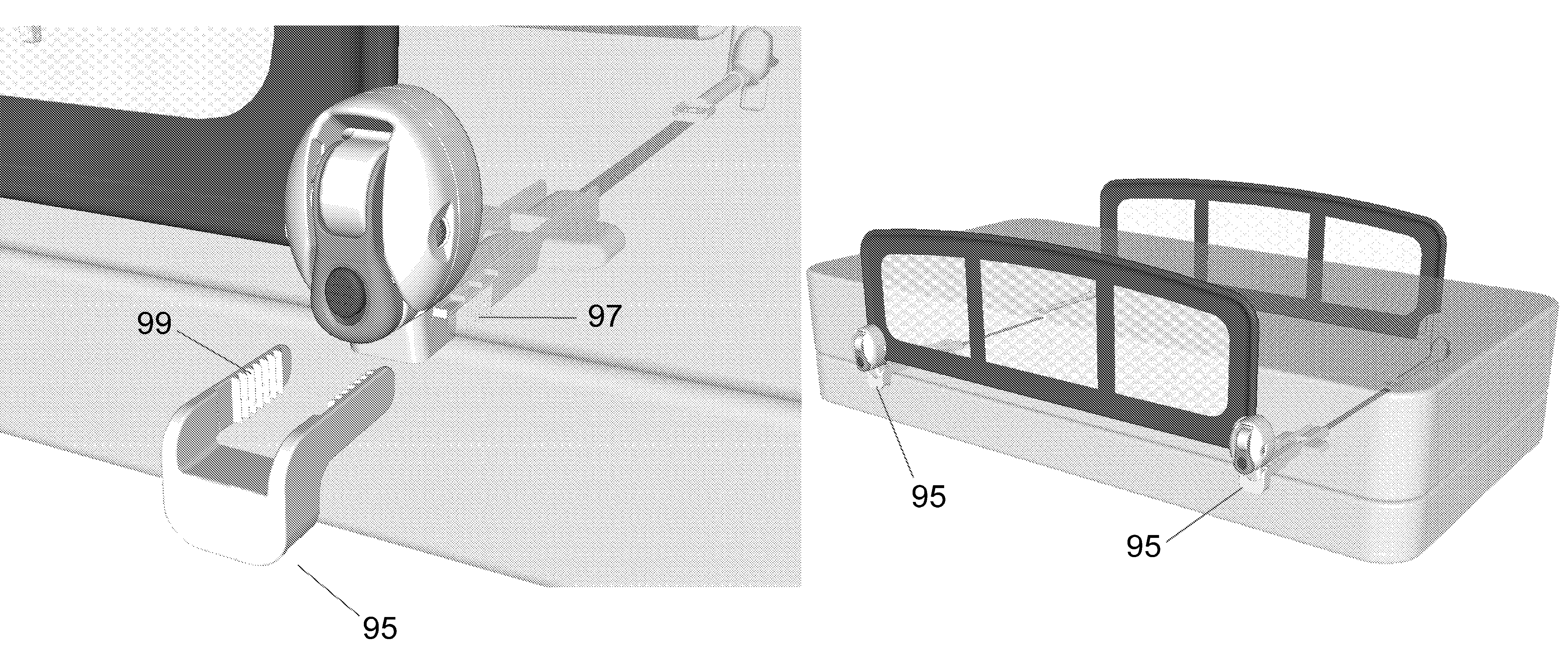
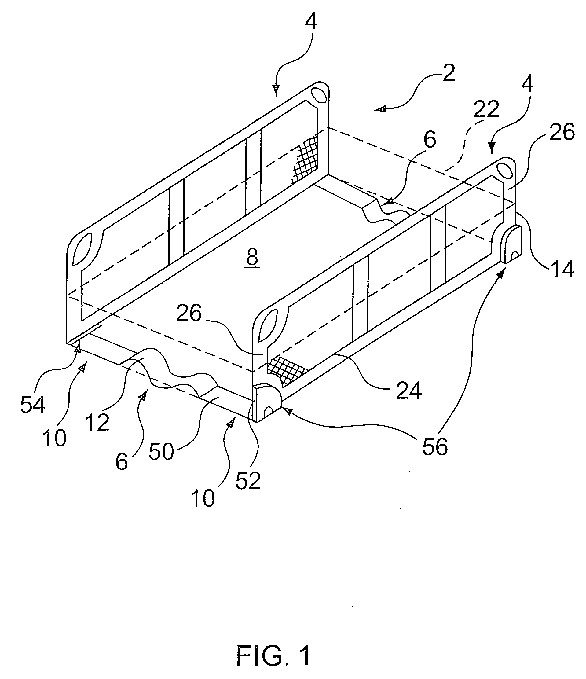
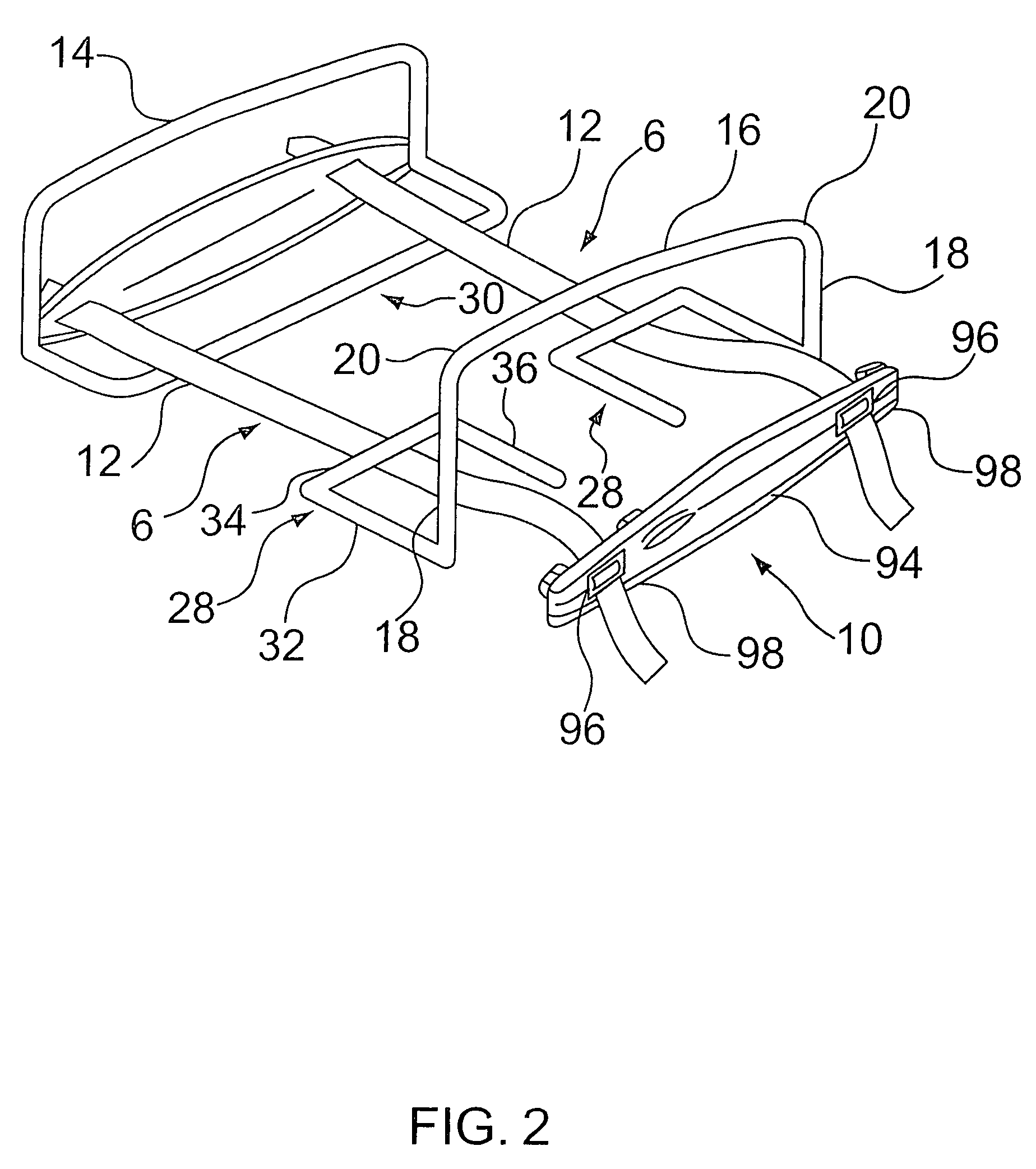
[0033]FIG. 1 shows a first exemplary embodiment of the bed guard assembly 2 of the present invention. This embodiment includes two end panels 4, flexible connecting material 6 for placement beneath a mattress 8, and connection pieces 10. As shown, the connection pieces 10 connect the flexible connecting material 6 to the end panels 4 such that at least one end panel opposes another end panel when the flexible connecting material 6 is disposed beneath a mattress 8. The flexible connecting material 6 can rest on a box spring located beneath the mattress 8, directly on the bed fame surface, on slats supporting the mattress 8, or on any other bedding element that might be present in the bedding configuration. Preferably, the end panels 4 extend vertically above the upper surface of the mattress 8.

[0034]The flexible connecting material 6 can include strips of webbing 12. As shown in FIG. 1, an exemplary embodiment includes two strips of webbing 12 material, connected to ends of the end p...


PUM


Abstract

A bed guard assembly includes a one or more end panels, a spanner, connectors and an extension. The spanner is placed against the top or bottom surface a mattress. The connectors connect the spanner to the end panels such that one end panel opposes another end panel across the mattress when the spanner is disposed against the surface of the mattress. The extension is removably attached to one of the connectors and extends from the connector at a substantially right angle with respect to the spanner.

Description

CROSS-REFERENCE TO RELATED APPLICATIONS[0001]This is based on U.S. Provisional Patent Application Ser. No. 60 / 623,752, which was filed on Oct. 29, 2004, which is a continuation-in-part of U.S. patent application Ser. No. 10 / 755,704, which was filed on Jan. 12, 2004, now U.S. Pat. No. 6,959,453, which in turn is a continuation-in-part of U.S. patent application Ser. No. 10 / 285,331, which was filed on Oct. 31, 2002, now U.S. Pat. No. 6,725,476, and which in turn was based on U.S. Provisional Patent Application Ser. No. 60 / 411,307, which was filed on Sep. 17, 2002.BACKGROUND OF THE INVENTION[0002]The present invention relates to guard assemblies for beds, used to prevent an occupant of the bed from falling off the bed.[0003]Bed guard assemblies, such as side rails, are well known. These assemblies are useful in several applications. For example, small children making the transition from sleeping in an enclosed crib to sleeping on an open bed often need a barrier to prevent a fall onto ...

Claims


Application Information

Patent Timeline
Patent Type & Authority Patents(United States)
IPC IPC(8): A47C21/08
CPCA47C21/08A61G7/0507A61G2007/0518A61G7/0518
Inventor MACARI, JASONGIBREE, STEVE
Owner SUMMER INFANT USA
Why Eureka
Try Eureka