Device comprising anterior plate for vertebral column support

a technology of anterior plate and vertebrae, which is applied in the direction of prosthesis, osteosynthesis devices, surgical staples, etc., can solve the problems of insufficient mechanical support provided by the device, major risk of sliding piece sliding and turning on the fastening rod, and not suited to anterolateral implantation on the lateral portion of the vertebrae, etc., to facilitate fitting and adjusting the position of the members, facilitate the fixing of the sliding piece, and facilitate the effect of fastening

Active Publication Date: 2008-11-25
LAPE MEDICAL
View PDF19 Cites 104 Cited by
  • Summary
  • Abstract
  • Description
  • Claims
  • Application Information

AI Technical Summary

Benefits of technology

[0009]The problem addressed by the present invention is that of designing a new structure for a device for treatment of the vertebral column using a smooth fastening rod and connecting sliding pieces for anchoring members that achieves significantly more effective fastening of the vertebrae, facilitates fitting and adjusting the position of the members relative to each other in three dimensions, and is also suited to fitting anterolaterally. One particular aim is to allow the fastening rod to be offered up and withdrawn by lateral displacement on a sliding piece already in position on a screw or other anchoring member to facilitate fixing the sliding piece to a vertebra, at the same time as improving its stability and to increase its capacity to absorb mechanical forces between successive vertebrae.
[0011]The two points in the vicinity of one end of the sliding piece and the anchoring screw engaged in the vicinity of the opposite end of the sliding piece provide stable fixing at three points in a triangular arrangement, which increases the stability of the device when fitted anterolaterally to the vertebral column, and allows positioning of the fastening rod closer to the rear of the vertebral column. At the same time, access to the tightening screws is facilitated.
[0013]The interior face of the sliding piece adapted to bear against the vertebra is preferably concave and substantially cylindrical with a circular profile. This promotes stability of the sliding piece on the vertebra.
[0014]To improve the retention of the sliding piece on the vertebra, each point extends in a substantially radial direction of the cylindrical interior face of the connecting sliding piece and the first hole has an axis that is substantially radial relative to the cylindrical interior face of the connecting sliding piece so that the point and the anchoring screw converge toward the vertebra.

Problems solved by technology

However, it is found that the mechanical support provided by this device is insufficient.
In particular, the direct bearing engagement of the sliding piece on a vertebra excludes all possibility of effective clamping, because of the low mechanical strength of the vertebra in compression, with the result that there is a major risk of the sliding piece sliding and turning on the fastening rod.
Also, this device is designed to be fitted to the posterior face of the vertebral column, and is not suited to anterolateral implantation on the lateral portion of the vertebrae.
Moreover, once the sliding piece is in position on the screw, it is no longer possible to engage the fastening rod laterally in the sliding piece.
The conical bearing surface of the nut bearing on the cylindrical shape of the fastening rod does not ensure sufficiently rigid fastening of the fastening rod.
Moreover, once the sliding piece is fixed to the screw by the nut it is no longer possible to engage the fastening rod laterally.
As a result of this it is relatively difficult to fit it anterolaterally and it is insufficiently stable in the vertebrae when high mechanical forces are applied between successive vertebrae.
It is not possible to offset the connecting rod described in that document toward the rear of the vertebral column either.
Their structures do not allow the connecting rods to be offset toward the rear of the vertebral column.

Method used


Image

  • Device comprising anterior plate for vertebral column support
  • Device comprising anterior plate for vertebral column support
  • Device comprising anterior plate for vertebral column support

Examples


Embodiment Construction

[0027]Consider first FIG. 6, which shows a device of the invention for supporting the vertebral column when fitted to a vertebral column.

[0028]The device of the invention for supporting the vertebral column comprises at least one connecting sliding piece 4 that connects an anchoring screw 1 to a fastening rod 3. The connecting sliding piece 4 is fixed to a vertebra 2 by the anchoring screw 1. Similarly, a second connecting sliding piece 4a is fixed to a second vertebra 2a by a second anchoring screw 1a. The fastening rod 3 is fixed to both connecting sliding pieces 4 and 4a so that the device provides a mechanical connection between the two vertebrae 2 and 2a.

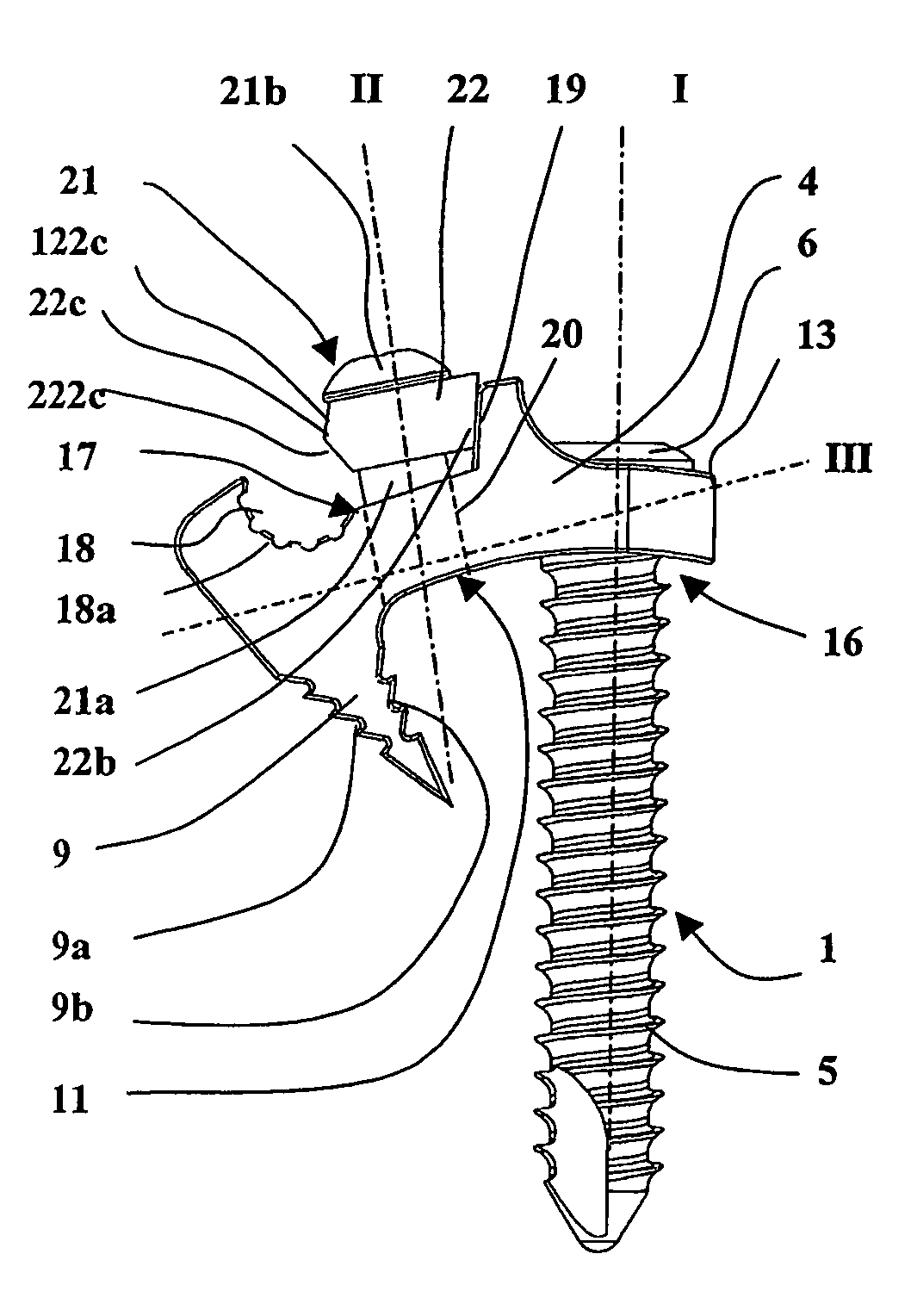
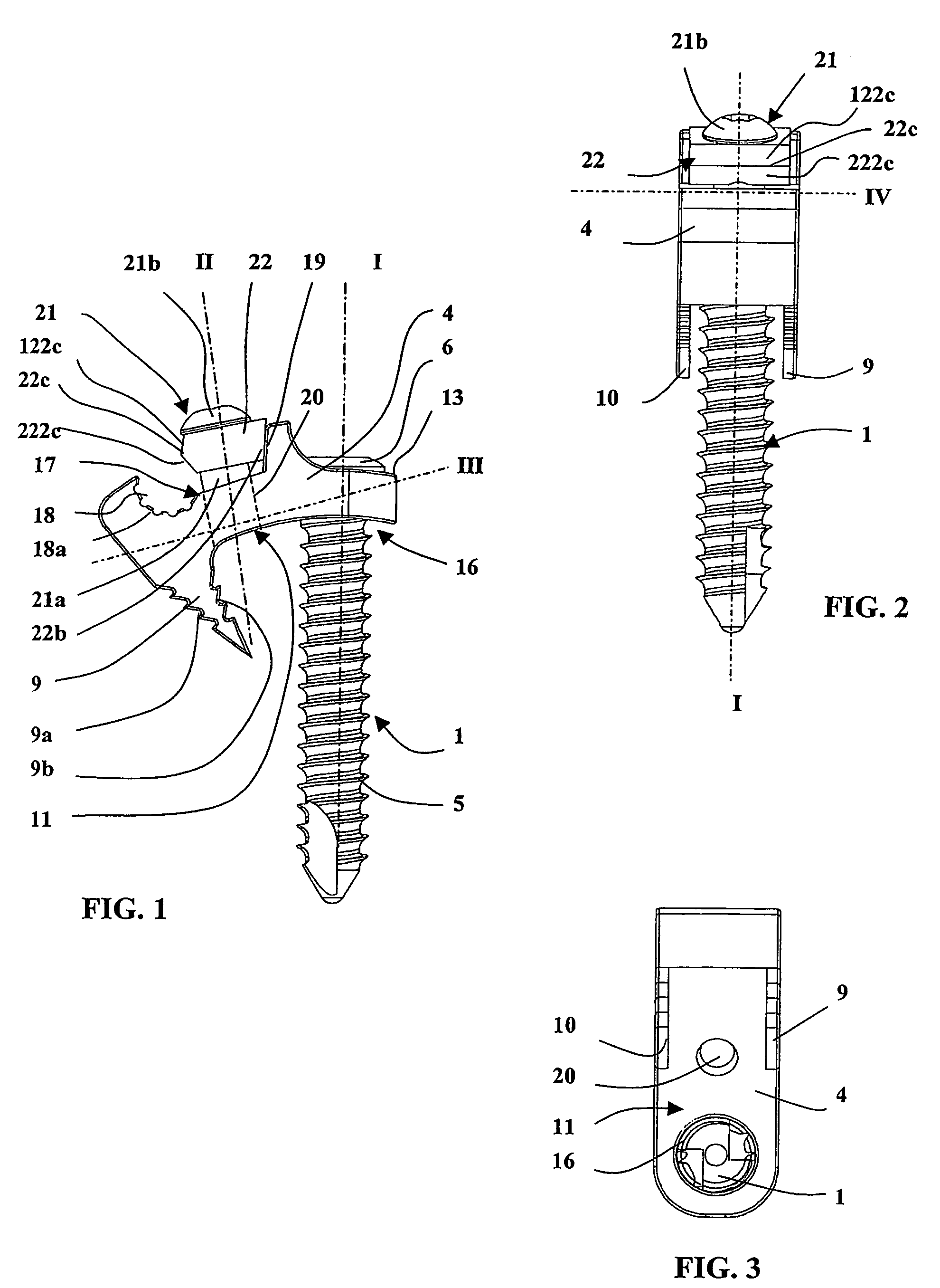
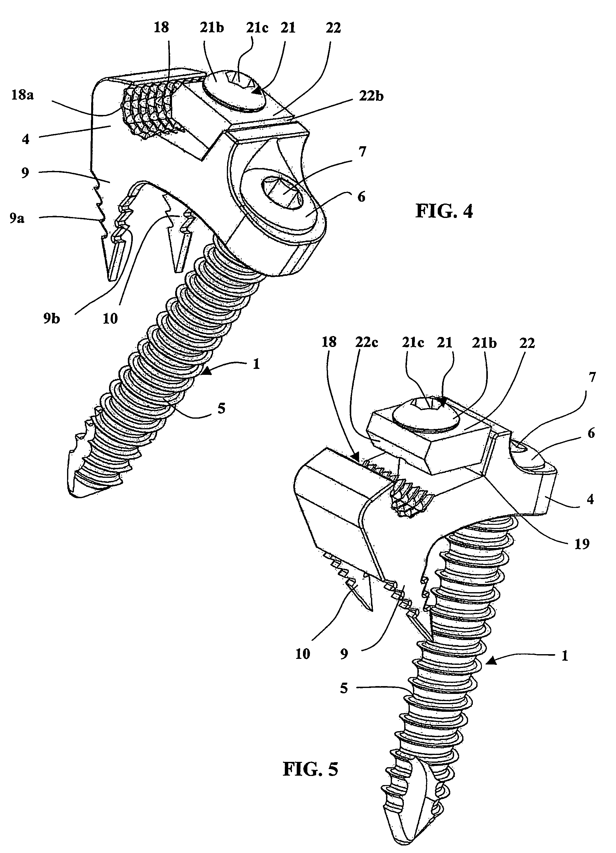
[0029]Refer now to FIGS. 1 to 5, which show the connecting sliding piece 4 and the anchoring screw 1.

[0030]The anchoring screw 1 comprises a threaded shank 5 conformed to be screwed into the bone of a vertebra and a head 6 with a hexagonal axial hole 7 adapted to have a screwing tool inserted into it.

[0031]The structure of the...


PUM


Abstract

In a device including an anterior plate for vertebral column support, there is at least one connecting sliding piece which is used to connect an anchoring screw to a securing rod. The securing rod is inserted into a cylindrical bearing and is fixed using a tightening device including a small clamp and a tightening screw. The connecting sliding piece includes at least one tip which extends away from the cylindrical bearing for the securing rod, in a direction which converges with the axis of the anchoring screw. In this way, the connecting sliding piece is provisionally fixed by pressing same against a vertebra, the anchoring screw is subsequently screwed in place and, finally, the securing rod is inserted laterally into the cylindrical bearing before being tightened using the small clamp and the tightening screw. The device is designed for anterior implantation on a vertebral column.

Description

TECHNICAL FIELD OF THE INVENTION[0001]The subject matter of the present invention is a device for supporting vertebrae in a required position. A device of this kind is used to treat a vertebral column having an abnormal deviation of degenerative or traumatic origin.[0002]Vertebral arthroses or fractures can be treated, for example, and vertebral column deviations such as scoliosis, lordosis and cyphosis corrected.[0003]The document U.S. Pat. No. 4,648,388 discloses a device for treatment of the vertebral column comprising elements anchored in the vertebrae, a fastening rod of circular section and having a smooth exterior surface, and connecting sliding pieces for connecting the anchoring members to the fastening rod. The anchoring members are screws having three main portions: a first end portion with a helicoidal thread adapted to penetrate and to be retained in bone, a smooth cylindrical intermediate portion of smaller diameter, and a second end portion with a helicoidal thread ad...

Claims


Application Information

Patent Timeline
Patent Type & Authority Patents(United States)
IPC IPC(8): A61B17/70
CPCA61B17/7041A61B17/7044A61B17/701A61B17/70A61B17/74
Inventor GRADEL, THOMASLEMAIRE, JEAN-PHILIPPE
Owner LAPE MEDICAL
Why Eureka
Try Eureka