Chiral fiber grating device and method of fabrication thereof

a fiber grating and fiber technology, applied in the field of fiber grating structures, can solve the problems of limiting the length of the resulting grating, limiting the produced index contrast, and the possibility of ruined custom preforms

Active Publication Date: 2008-12-09
CHIRAL PHOTONICS
View PDF2 Cites 25 Cited by
  • Summary
  • Abstract
  • Description
  • Claims
  • Application Information

AI Technical Summary

Problems solved by technology

This approach limits the length of the resulting grating and also limits the produced index contrast.
Furthermore, such equipment requires perfect alignment of the lasers and exact coordination of the fiber over minute distances when it is displaced prior to being exposed again to the laser beam.
However, one of the challenges of fabricating chiral fiber gratings in accordance with the CFF Patent Applications, is preparation of proper optical fiber preforms used in fabrication of the gratings.
Another challenge rests in fabrication of certain types of chiral fiber gratings, for example those with properties.
Such gratings require twist and drawing fabrication protocols that vary during the fabrication process, and thus cause additional stress on the fiber increasing the likelihood that a custom preform may be ruined.

Method used


Image

  • Chiral fiber grating device and method of fabrication thereof
  • Chiral fiber grating device and method of fabrication thereof
  • Chiral fiber grating device and method of fabrication thereof

Examples


Embodiment Construction

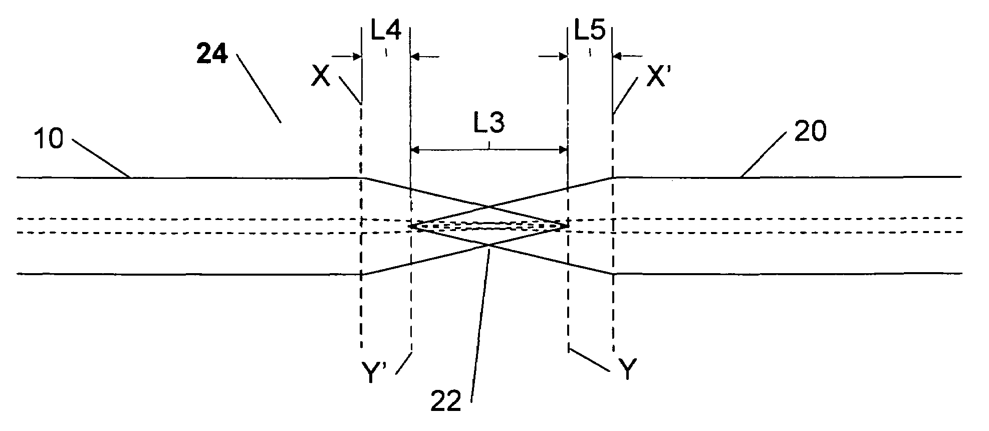
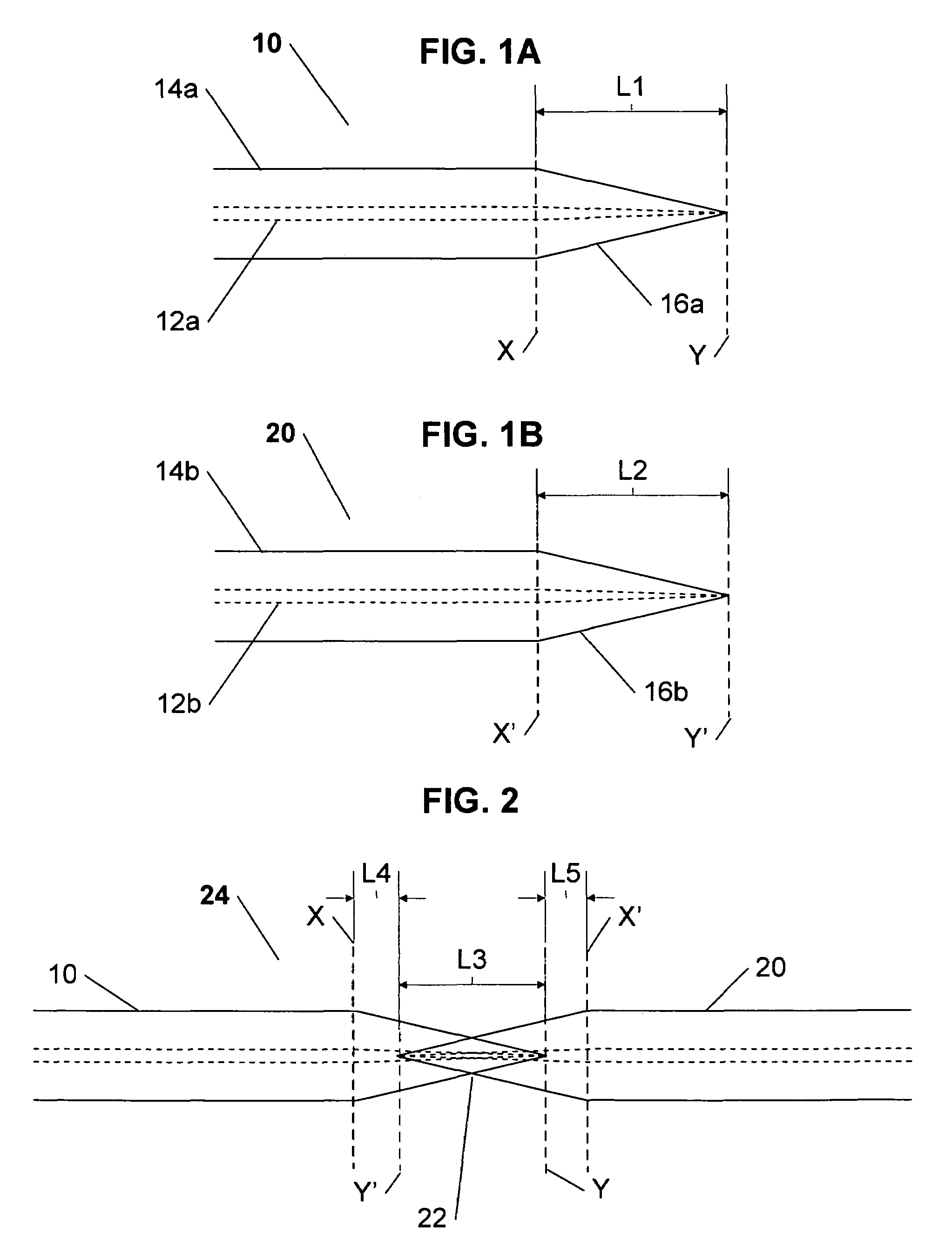
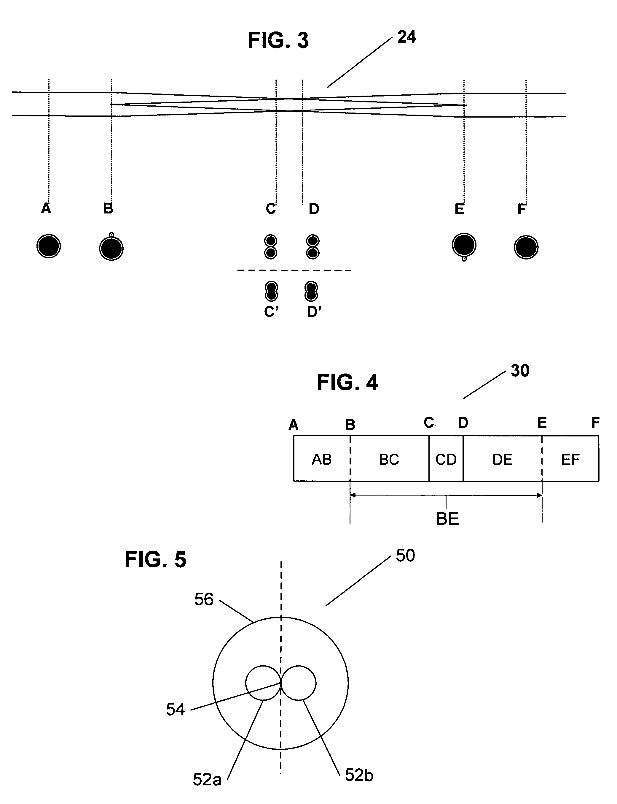
[0019]The present invention is directed to a custom chiral fiber grating for reflecting, scattering or polarizing an optical signal or for forming a fiber laser feedback structure, and an advantageous method of fabrication thereof. In essence, the inventive chiral fiber grating is fabricated by fusing and then twisting / drawing two tapered optical fibers in accordance with a predetermined fabrication protocol. In one embodiment of the invention, the chiral fiber grating includes two single helix structure end-regions, with a double helix structure therebetween, providing the grating with apodizing properties. In another embodiment of invention, the pitch profile along a portion of the grating is configured to produce desired chiral fiber grating properties. In yet another embodiment of the invention, the chiral fiber grating comprising two single helix end regions and a middle double helix region may be separated into two or more portions after fabrication, for example to provide one...


PUM

PropertyMeasurementUnit
grating strengthaaaaaaaaaa
structureaaaaaaaaaa
birefringence profileaaaaaaaaaa

Abstract

A chiral fiber grating for reflecting, scattering or polarizing an optical signal, or for forming a fiber laser feedback structure is disclosed. The chiral fiber grating is fabricated by fusing and then twisting / drawing two tapered optical fibers in accordance with a predetermined fabrication protocol. In one embodiment of the invention, the chiral fiber grating includes two single helix structure end-regions, with a double helix structure therebetween, providing the grating with apodizing properties. In another embodiment of invention, the pitch profile along a portion of the grating is configured to produce desired chiral fiber grating properties. In yet another embodiment of the invention, the chiral fiber grating, comprising two single helix end regions and a middle double helix region, may be separated into two or more portions after fabrication, for example to provide one or more single helix chiral fiber gratings and one or more double helix chiral fiber gratings. In an alternate embodiment of the invention, a double helix structure chiral fiber grating is provided by twisting two parallel optical fibers around a longitudinal central axis positioned therebetween.

Description

CROSS REFERENCE TO RELATED APPLICATIONS[0001]The present patent application claims priority from the commonly assigned provisional patent application Ser. No. 60 / 754,591 entitled “Chiral Fiber Grating Device and Method of Fabrication Thereof”, filed Dec. 27, 2005.FIELD OF THE INVENTION[0002]The present invention generally relates to fiber grating structures, and a method of manufacturing thereof, for utilization as dielectric waveguides for signal generation and processing, and more particularly to an optical fiber grating having chiral properties that is fabricated fusing and then twisting two optical fibers under a predetermined fabrication protocol.BACKGROUND OF THE INVENTION[0003]Fiber gratings are incorporated into components that form the backbone of modern information and communications technologies, and are suitable for a wide range of applications, such as information processing and optical fiber communication systems utilizing wavelength division multiplexing (WDM). There ...

Claims


Application Information

Patent Timeline
Patent Type & Authority Patents(United States)
IPC IPC(8): G02B6/34
CPCG02B6/02085G02B6/02123G02B6/2552G02B2006/0209
Inventor KOPP, VICTOR IL'ICHGENACK, AZRIEL ZELIGZHANG, GUOYIN
Owner CHIRAL PHOTONICS
Why Eureka
Try Eureka