Warning system for child restraint system

a child restraint and warning system technology, applied in the field of electric communication, can solve the problems of children receiving a staggering amount of damage, loss of the ability to read and write, and memory impairment,

Inactive Publication Date: 2008-12-16
LEHR SCOTT K
View PDF14 Cites 52 Cited by
  • Summary
  • Abstract
  • Description
  • Claims
  • Application Information

AI Technical Summary

Problems solved by technology

Children receive a staggering amount of damage during an automobile accident.
Damage to a child's brain may leads to memory impairment, educational dysfunction, and the loss of the ability to read and write.
These force trauma injuries may lead to emotional disturbances such as hyperactivity, apathy, or inattentiveness.
From 1898 to the 1960s, child car seats were designed to restrain a child in place while a vehicle was in motion, but not necessarily keep the child safe from harm.
Accelerating the human body relative to the interior of an automobile is what causes injuries in the crash.
If the harness or seat belt were to become released while the car is in motion, then the child restraint system would not provide the child any restraint or safety from a car crash.
It is an unfortunate fact that children sometimes release the harness to their safety seat not knowing the horrific dangers they fact.
Moreover, the seat belt holding the car seat sometimes is released accidentally and unknowingly by riders sitting in the center back seat next to the seat belt holding the car seat.
The potential of this happening may cause anxiety and tension in most parents, not only because of the safety issue but because parents will receive expensive tickets if their child is not properly restrained.
A drawback of this is that the parent is not able to concentrate fully on the task of driving.
If not properly connected, an alarm may sound.

Method used


Image

  • Warning system for child restraint system
  • Warning system for child restraint system
  • Warning system for child restraint system

Examples


Embodiment Construction

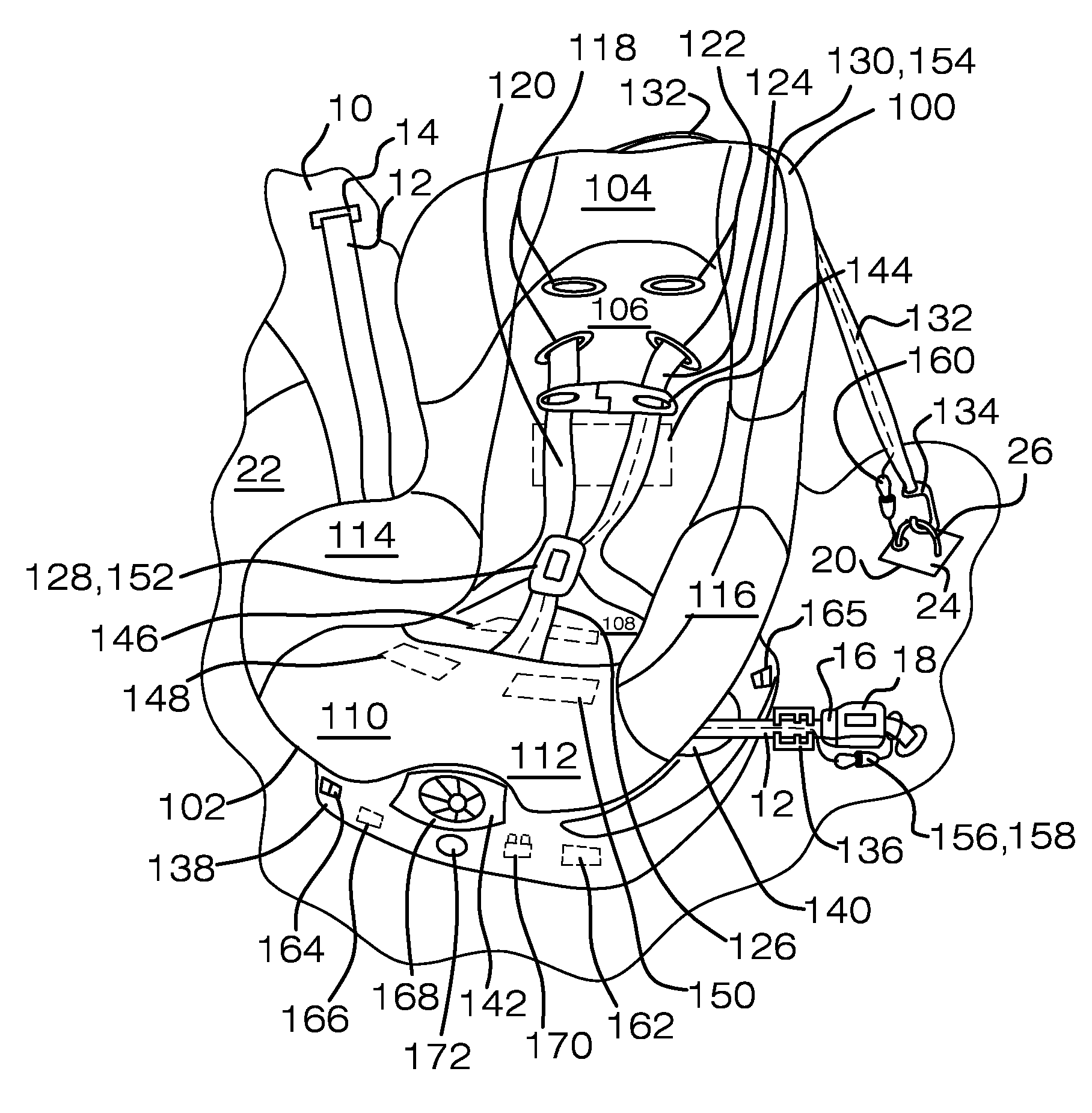
[0017]FIG. 1 is an isometric view of a child restraint system 100 in a vehicle 10. Child restraint system 100 may be a restraint system equipped with safety straps to hold a child in a seated position in vehicle 10. As set out in more detail below, child restraint system 100 may include sensors that may respond to relative conditions between a child, child restraint system 100, and vehicle 10 by providing humanly perceptible signals in response to the attainment of predetermined conditions.

[0018]Vehicle 10 may include a lap / shoulder belt 12 extending from a back seat retractor 14 and having a lap / shoulder belt buckle tongue 16 configured to mate to a vehicle seat belt buckle 18 secured to vehicle 10. Vehicle 10 additionally may include a latch anchor 20 and door 22. Latch anchor 20 may have a metal plate 24 attached to vehicle 10 and latch anchor ring 26 attached to metal plate 24. Generally, lap / shoulder belt 12 and latch anchor 20 may aid in securing child restraint system 100 to ...


PUM


Abstract

This patent discloses a warning system for a child restraint system. The child restraint system may include a base and a seat connected to the base. The seat may include supports for the back, torso, right leg, and left leg and may include sensors to detect the presence of a back, torso, right leg, and left leg, respectively. The seat also may include a right harness strap and a left harness strap that may connect to a child seat buckle and to a chest clip. The seat also may have a locking clip a tether strap having a hook. The seat may contain detectors to determine whether the straps, buckles, clips, and straps are properly connected while a is present in the seat. If not properly connected, an alarm may sound.

Description

BACKGROUND[0001]1. Field of Endeavor[0002]The information disclosed in this patent relates to electrical communications and more particularly to sensors that may respond to relative conditions between a child, a child car seat, and a vehicle by providing humanly perceptible signals in response to the attainment of predetermined conditions.[0003]2. Background Information[0004]Children receive a staggering amount of damage during an automobile accident. Damage to a child's brain may leads to memory impairment, educational dysfunction, and the loss of the ability to read and write. These force trauma injuries may lead to emotional disturbances such as hyperactivity, apathy, or inattentiveness. Most horrific, a child is much more likely than an adult to die during a car crash.[0005]Early on, child car seats have been designed to mitigate injury to children involved in car crashes. From 1898 to the 1960s, child car seats were designed to restrain a child in place while a vehicle was in m...

Claims


Application Information

Patent Timeline
Patent Type & Authority Patents(United States)
IPC IPC(8): B60Q1/00
CPCB60N2/2812B60R22/48B60R22/105B60R2022/4816B60R2022/4866B60N2002/2815
Inventor LEHR, SCOTT K.
Owner LEHR SCOTT K
Why Eureka
Try Eureka