Sparse trifilar array antenna

Inactive Publication Date: 2008-12-16
LOCKHEED MARTIN CORP
View PDF5 Cites 15 Cited by
  • Summary
  • Abstract
  • Description
  • Claims
  • Application Information

AI Technical Summary

Benefits of technology

[0007]The present invention addresses the foregoing concerns by providing an array antenna having an innovative sparse trifilar configuration. The antenna elements are arranged in three non-linear arrays that are separated from each other by vacant positions in the configuration. This sparse configuration uses one half of the number of antenna elements required to fully populate a conventional array, while maintaining approximately the same directivity and beamwidth. The inventive arrangement of arranging array elements in a sparse trifilar array configuration reduces the symmetry of larger arrays comprising multiple sparse trifilar arrays. The inventive arrangement also minimizes grating lobes in the radiation pattern of the larger array antennas.

Problems solved by technology

If a sparse array is used to obtain the larger aperture size, however, grating lobes can be generated in the radiation pattern thereby reducing the directivity of the array antenna.
However, when both signals pass through a non-linear circuit within the array antenna, intermodulation products from third order mixing can cause spurious signals to appear in or near the pass-bands associated with the intended transmission signals.

Method used


Image

  • Sparse trifilar array antenna
  • Sparse trifilar array antenna
  • Sparse trifilar array antenna

Examples


Embodiment Construction

[0018]The invention will now be described more fully with reference to the accompanying drawings, wherein like reference numerals refer to like elements throughout the drawings. The following description includes preferred embodiments of the invention provided to describe the invention by way of example to those skilled in the art.

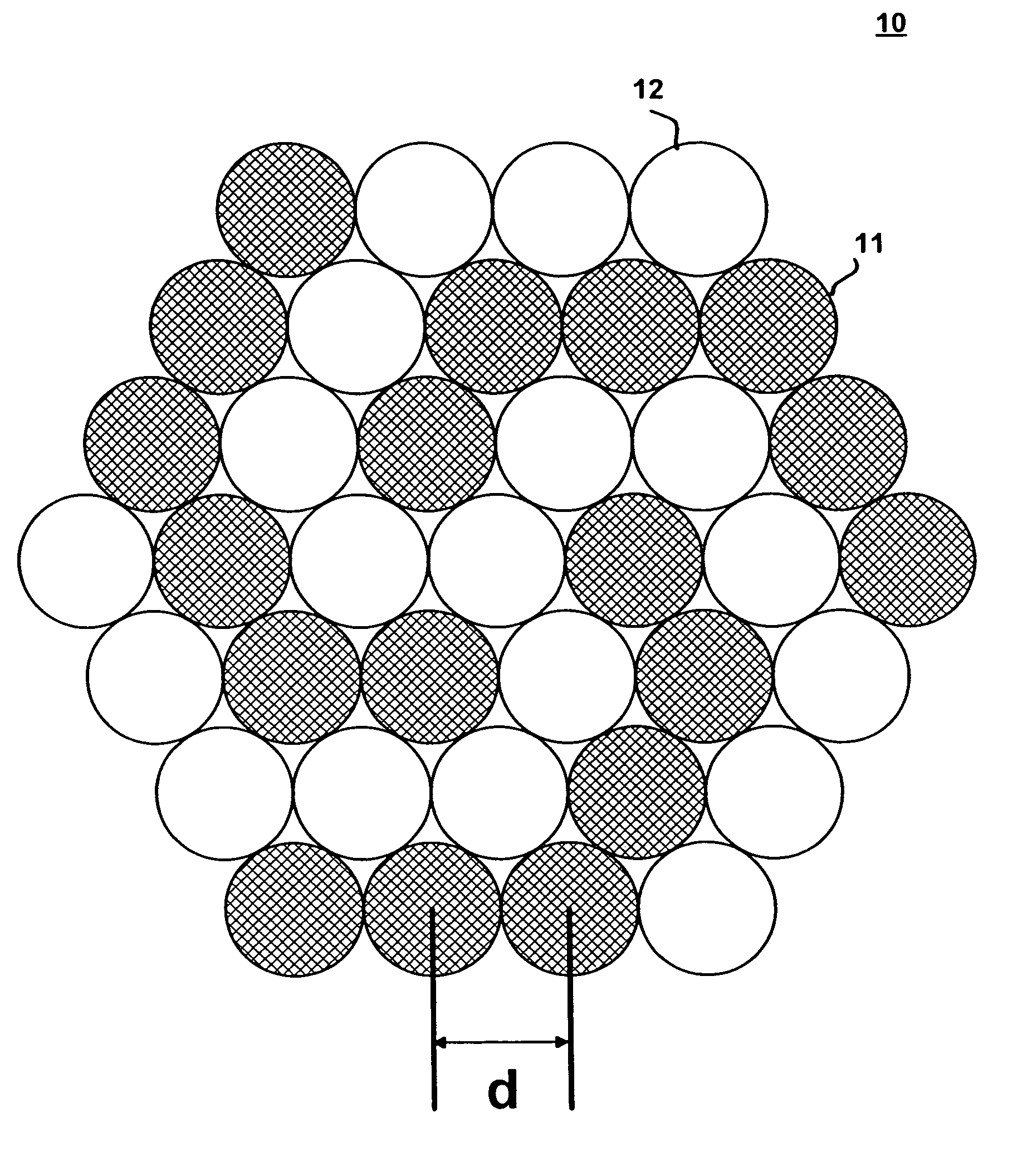
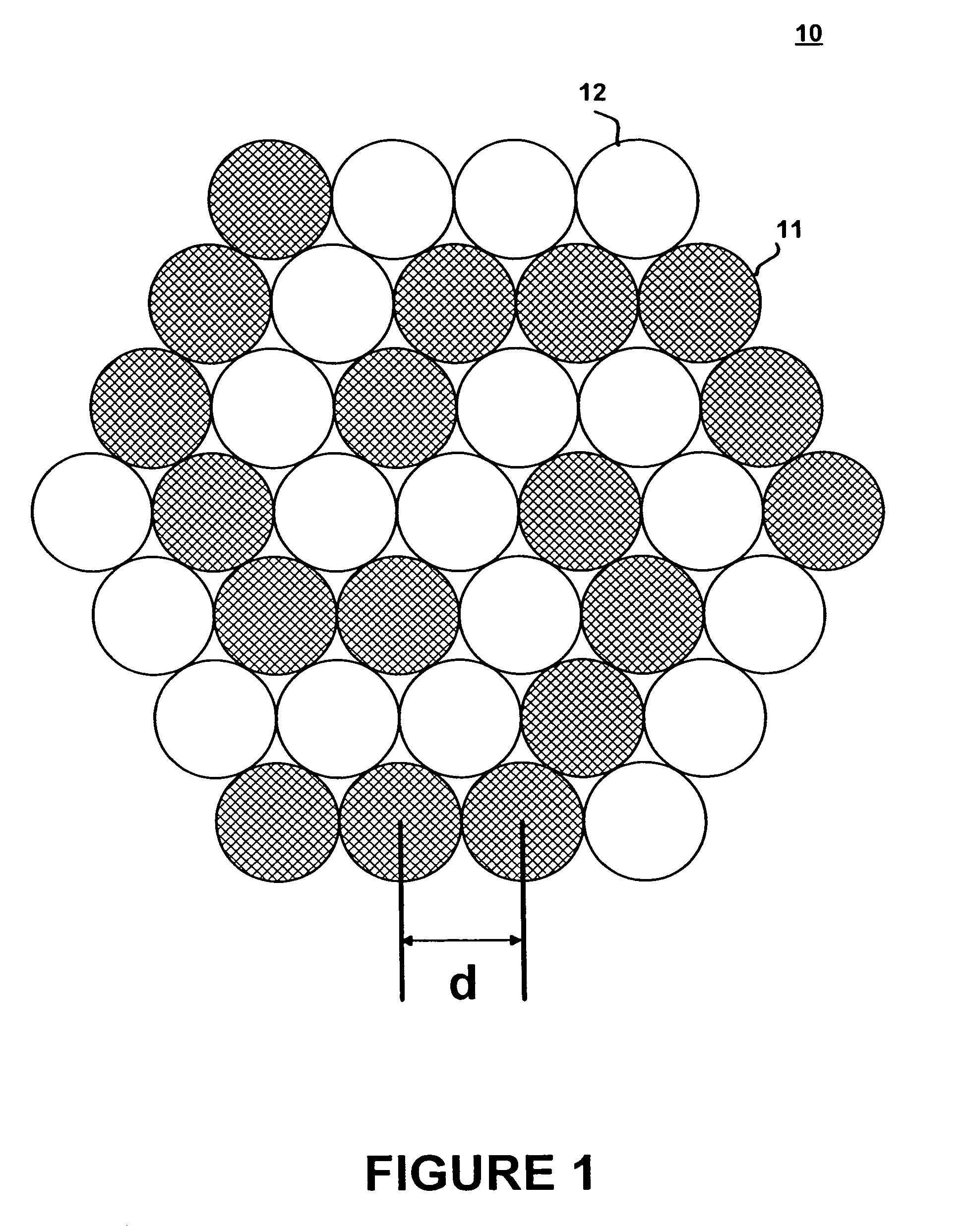
[0019]FIG. 1 is a diagram depicting an array antenna configuration according to one embodiment of the present invention. As shown in FIG. 1, array antenna 10 comprises eighteen antenna elements 11 which are depicted in the drawing as cross-hatched circles. Antenna elements 11 are arranged in three non-linear arrays, with each array comprising six antenna elements. The three arrays represent a trifilar configuration. The number and arrangement of antenna elements 11 depicted in FIG. 1 represents only one embodiment of the invention. Alternative embodiments of the invention may include more or less than eighteen antenna elements in the configuration with mor...


PUM


Abstract

An array antenna is arranged in an innovative sparse trifilar configuration. The antenna elements forming the array antenna are arranged to form three non-linear arrays. The antenna elements are approximately aligned to a triangular lattice structure with the antenna elements of each non-linear array occupying adjacent lattice positions. The three non-linear arrays are separated from each other by vacant lattice positions, thereby making the configuration a sparse array.

Description

STATEMENT REGARDING FEDERALLY SPONSORED RESEARCH OR DEVELOPMENT[0001]Not applicable.FIELD OF THE INVENTION[0002]The present invention concerns electronically scanned array antennas, and, in particular, an electronically scanned array antenna having a trifilar configuration.BACKGROUND OF THE INVENTION[0003]Electronically scanned array antennas are commonly used in air, space and ground communication systems. These array antennas comprise multiple antenna elements whose radiation patterns are constructively combined to form antenna beams. By controlling the phase and / or amplitude of the signal fed to the individual antenna elements, the generated antenna beams are electronically shaped and scanned in a desired direction. Because the antenna beam is controlled electronically, these array antennas require minimal mechanical structure and moving parts, and are preferred for use on satellite communication systems.[0004]The radiation pattern of an array antenna is the product of the array ...

Claims


Application Information

Patent Timeline
IPC IPC(8): H01Q1/36
CPCH01Q21/061H01Q21/22
Inventor LAM, LAWRENCE K.NGO, ALBERT T.MAHMOUD, MOHAMED S.PELOQUIN, MARC L.
Owner LOCKHEED MARTIN CORP
Why Eureka
Try Eureka