Triangular apertures with embedded trifilar arrays

Active Publication Date: 2014-07-15
LOCKHEED MARTIN CORP
View PDF6 Cites 19 Cited by
  • Summary
  • Abstract
  • Description
  • Claims
  • Application Information

AI Technical Summary

Benefits of technology

[0011]In one embodiment, the trifilar subarrays are sparse trifilar subarrays, allowing implementation with one-half of the number of antenna elements required to fully populate a conventional array, while maintaining approximately the same beamwidth. The inventive arr

Problems solved by technology

If a sparse array is used to obtain the larger aperture size, however, grating lobes can be generated in the radiation pattern thereby reducing the directivity of the array antenna.
However, when both signals pass through a twodimensional circuit within the arr

Method used


Image

  • Triangular apertures with embedded trifilar arrays
  • Triangular apertures with embedded trifilar arrays
  • Triangular apertures with embedded trifilar arrays

Examples


Embodiment Construction

[0021]The following detailed description and appended drawings describe and illustrate various embodiments of the invention. The description and drawings serve to enable one skilled in the art to make and use the invention, and are not intended to limit the scope of the invention in any manner.

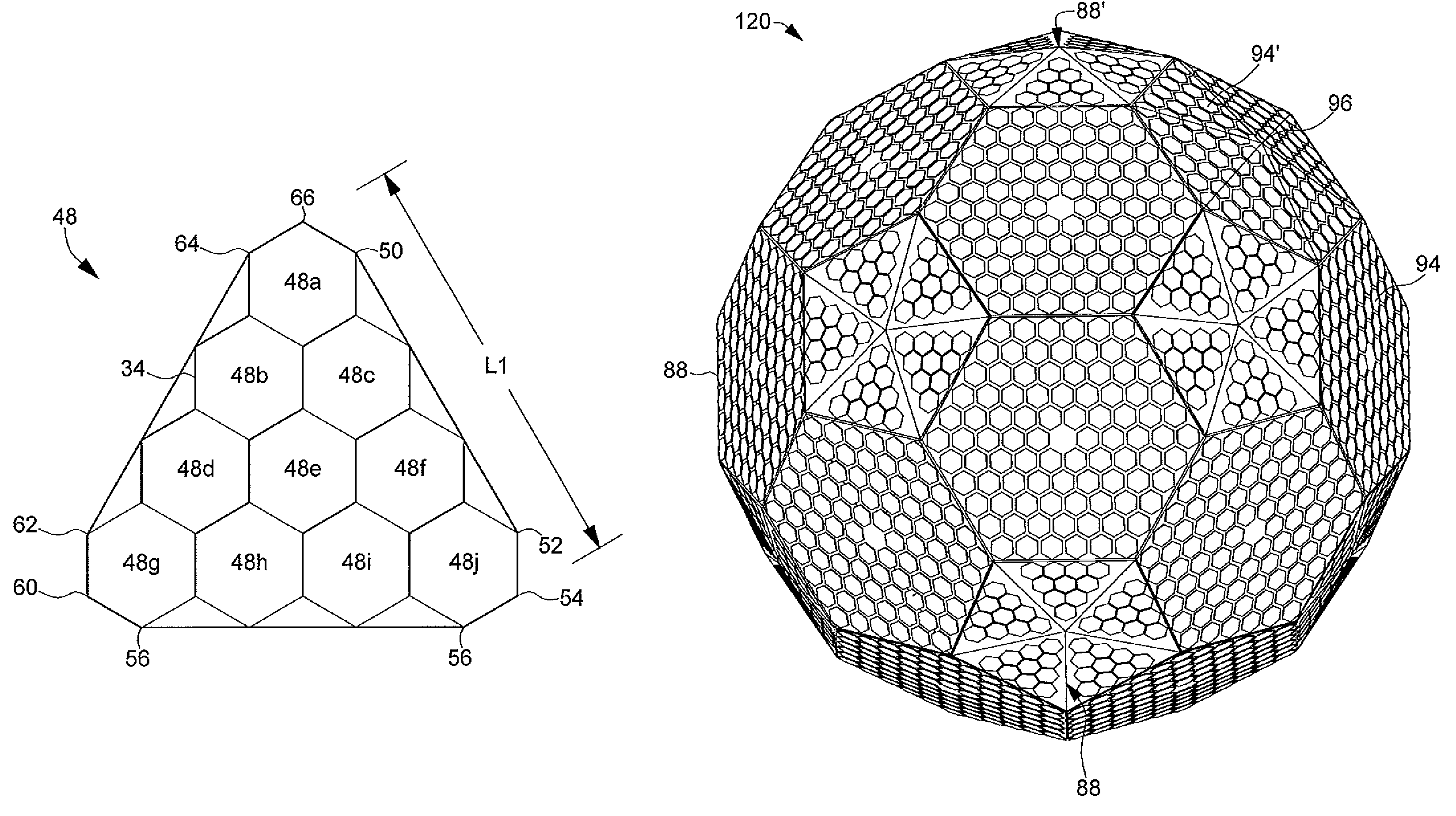
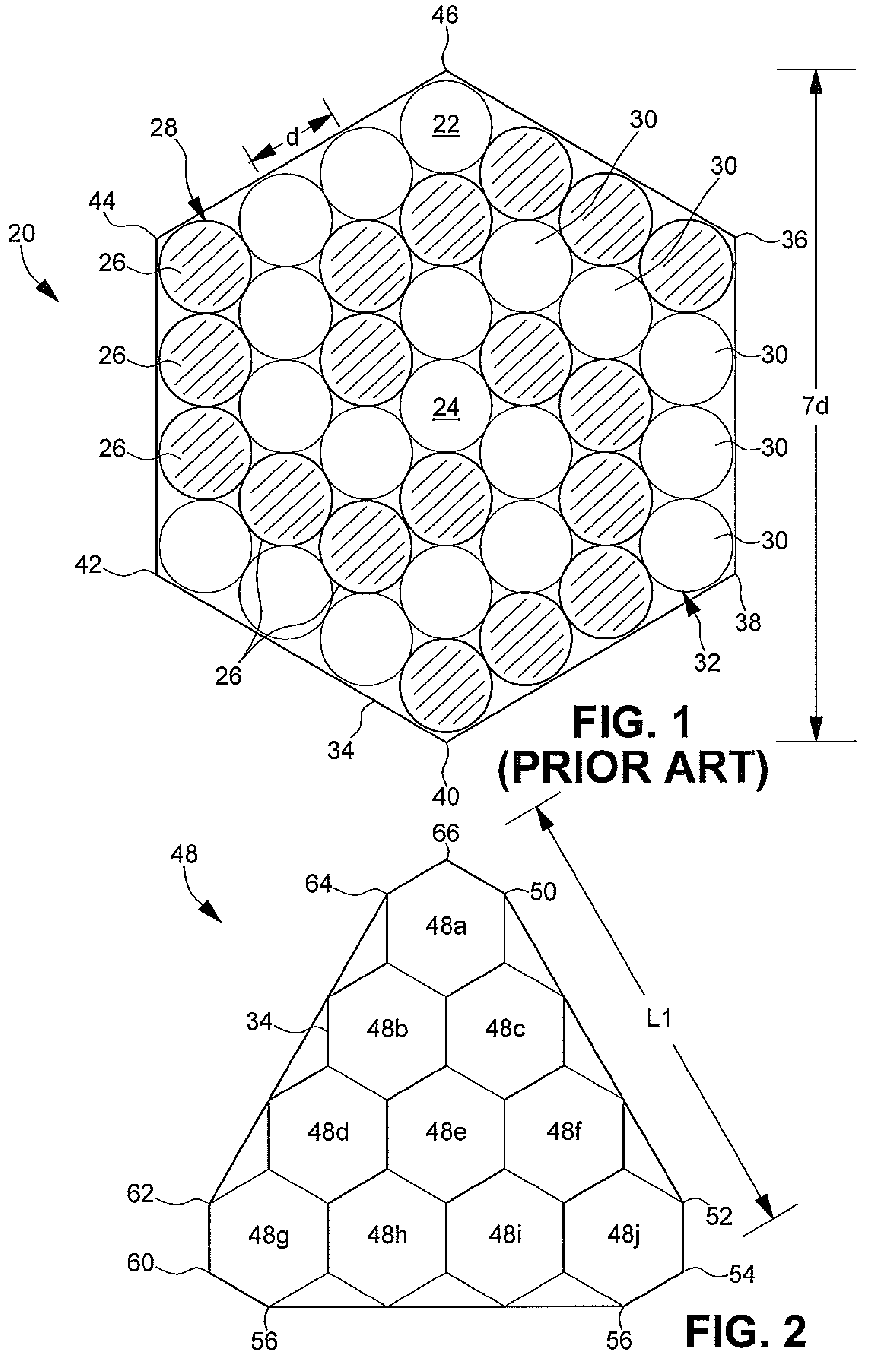
[0022]The trifilar subway 20 that forms the basic building block for the present invention is shown in FIG. 1, multiple embodiments of which are fully described in commonly owned U.S. Pat. No. 7,466,287. The trifilar subarray 20 is comprised of a plurality of antenna elements 22 arranged in an efficient triangular lattice structure having a center-to-center spacing d. In FIG. 1, a total of 36 antenna elements 22 are combined, with a vacant lattice position 24 centrally located within the trifilar subarray 20. It is understood that the total number of antenna elements 22 that form the trifilar subarray 20 may be more or less than 36 antenna elements. In particular, a “sparse” configuration of a...


PUM


Abstract

A first plurality of antenna elements is arranged in a lattice structure to form trifilar subarrays having a generally hexagonal perimeter. A second plurality of the trifilar subarrays is arranged into substantially equilateral triangular facets that may be combined into substantially planar elements to create geometric apertures of a conformal antenna structure. The geometric apertures may be combined to form conformal antennas approximating hemispherical, spherical or cylindrical structures.

Description

STATEMENT REGARDING FEDERALLY SPONSORED RESEARCH OR DEVELOPMENT[0001]Not applicable.CROSS-REFERENCE TO RELATED APPLICATIONS[0002]The present application claims priority to U.S. Provisional Application Ser. No. 61 / 169,547 filed Apr. 15, 2009.FIELD OF THE INVENTION[0003]The invention relates to electronically scanned array antennas. In particular, the invention relates to conformal three-dimensional antennas having triangular apertures with embedded trifilar arrays.BACKGROUND OF THE INVENTION[0004]Electronically scanned array (“ESA”) antennas are commonly used in air, space and ground communication systems. These array antennas comprise multiple antenna elements whose radiation patterns are constructively combined to form antenna beams. By controlling the phase and / or amplitude of the signal fed to the individual antenna elements, the generated antenna beams are electronically shaped and scanned in a desired direction. Because the antenna beam is controlled electronically, these array...

Claims


Application Information

Patent Timeline
IPC IPC(8): H01Q21/20H01Q1/28H01Q3/24H01Q21/06
CPCH01Q21/205H01Q1/288H01Q21/061H01Q25/00H01Q3/24
Inventor LAM, LAWRENCE K.WALDBAUM, SAMUEL J.
Owner LOCKHEED MARTIN CORP
Why Eureka
Try Eureka