System and method for providing proxy and translation domains in a fibre channel router
What is AI technical title?
AI technical title is built by PatSnap AI team. It summarizes the technical point description of the patent document.
a technology of fibre channel router and proxy domain, applied in the field of storage area networking, to achieve the effect of improving the management of the entire network and facilitating the interconnection of devices
Inactive Publication Date: 2008-12-16
AVAGO TECH INT SALES PTE LTD
View PDF28 Cites 84 Cited by
Summary
Abstract
Description
Claims
Application Information
AI Technical Summary
This helps you quickly interpret patents by identifying the three key elements:
Problems solved by technology
Method used
Benefits of technology
Benefits of technology
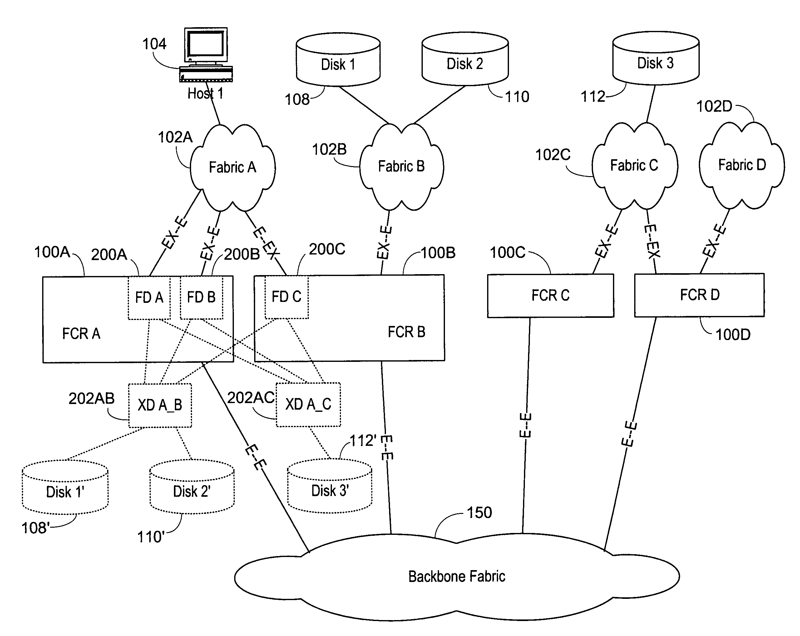
[0009]A Fibre Channel router according to the present invention can be used to join isolated Fibre Channel fabrics to allow greater interconnection of devices and overall improved manageability of the entire network. In a first embodiment the Fibre Channel router contains EX_ports to connect to each of the existing fabrics. The EX_port is a new port developed to have the port join the fabric but not to have the router itself merge into the fabric. Thus the Fibre Channel router can have ports that are members of multiple fabrics. The Fibre Channel router will translate addresses between the particular fabrics so that devices in the different fabrics can communicate.
[0012]One complexity arises because phantom or proxy domains and devices must be developed for each of the fabrics being interconnected, so that the devices on a particular fabric are not aware of the various translations which must occur. To this end, each Fibre Channel router has at least two domains that it develops. A first set of domains is the front phantom domains. These are domains present at each port directly connected to a fabric. Each of these front phantom domains is then connected to at least one translate phantom domain, there being one translate phantom domain for each particular fabric to which devices being translated are connected. The use of the front phantom domains for each connected port and a translate phantom domain for each connected fabric simplifies overall routing operations and provides redundancy and simplification of the software required.
Problems solved by technology
One complexity arises because phantom or proxy domains and devices must be developed for each of the fabrics being interconnected, so that the devices on a particular fabric are not aware of the various translations which must occur.
Method used
Image
Click on the blue label to locate the original text in one second.
Reading with bidirectional positioning of images and text.
Examples
Embodiment Construction
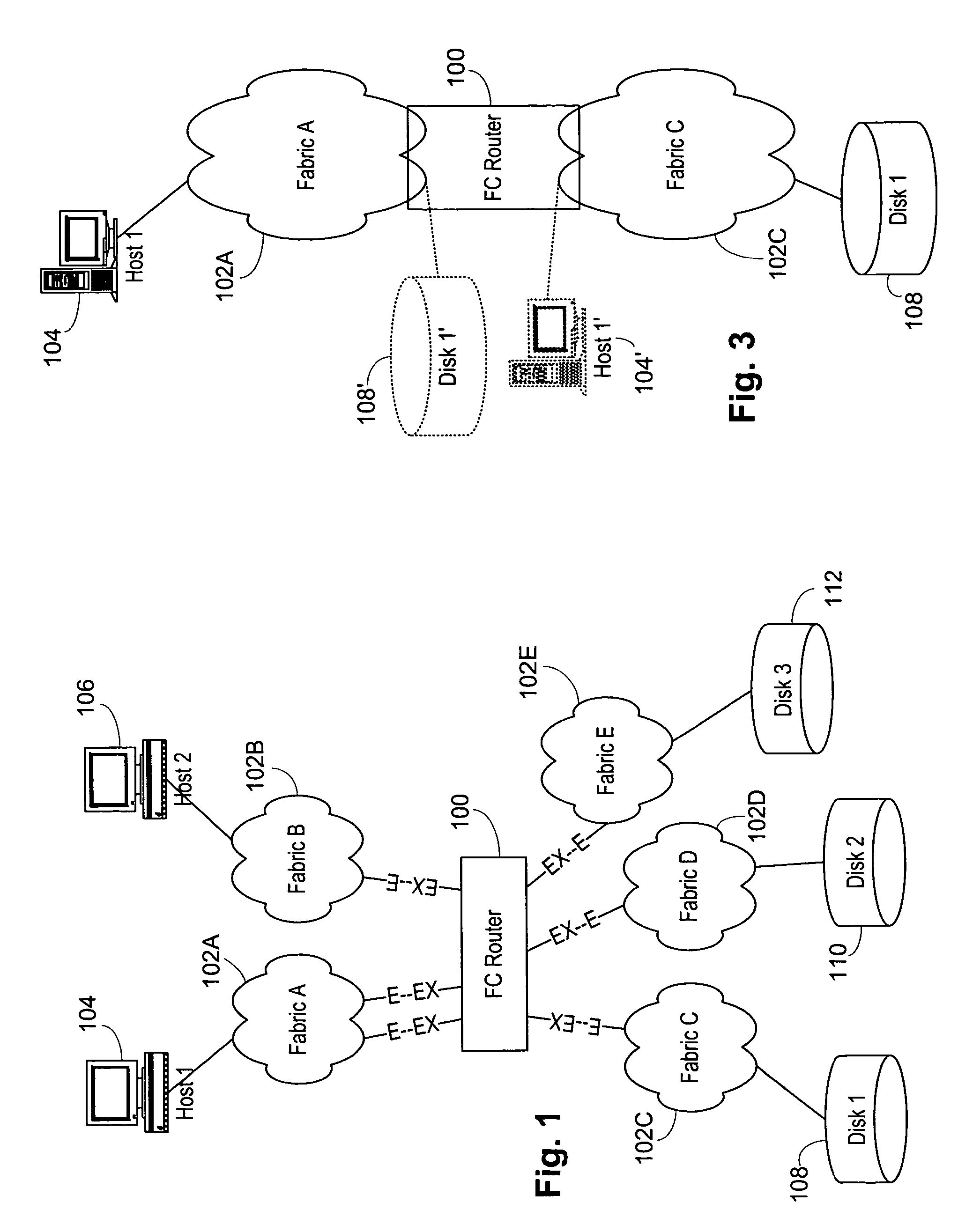
[0039]Referring now to FIG. 1, a Fibre Channel router 100 according to the present invention connected to a series of fabrics A-E 102A-102E by a series of links where a switch in each of the fabrics A-E 102A-102E has an E_port connected to an EX_port of the Fibre Channel router 100. An EX_port is, in great respects, an E_port but it does not cause the merger of the remainder of the Fibre Channel router 100 with the connected edge fabric 102. A host 104 is connected to fabric A 102 A, while a host 106 is connected to a fabric B 102 B. Similarly, storage devices 108, 110 and 112 are connected to fabrics C-E 102C-102E.
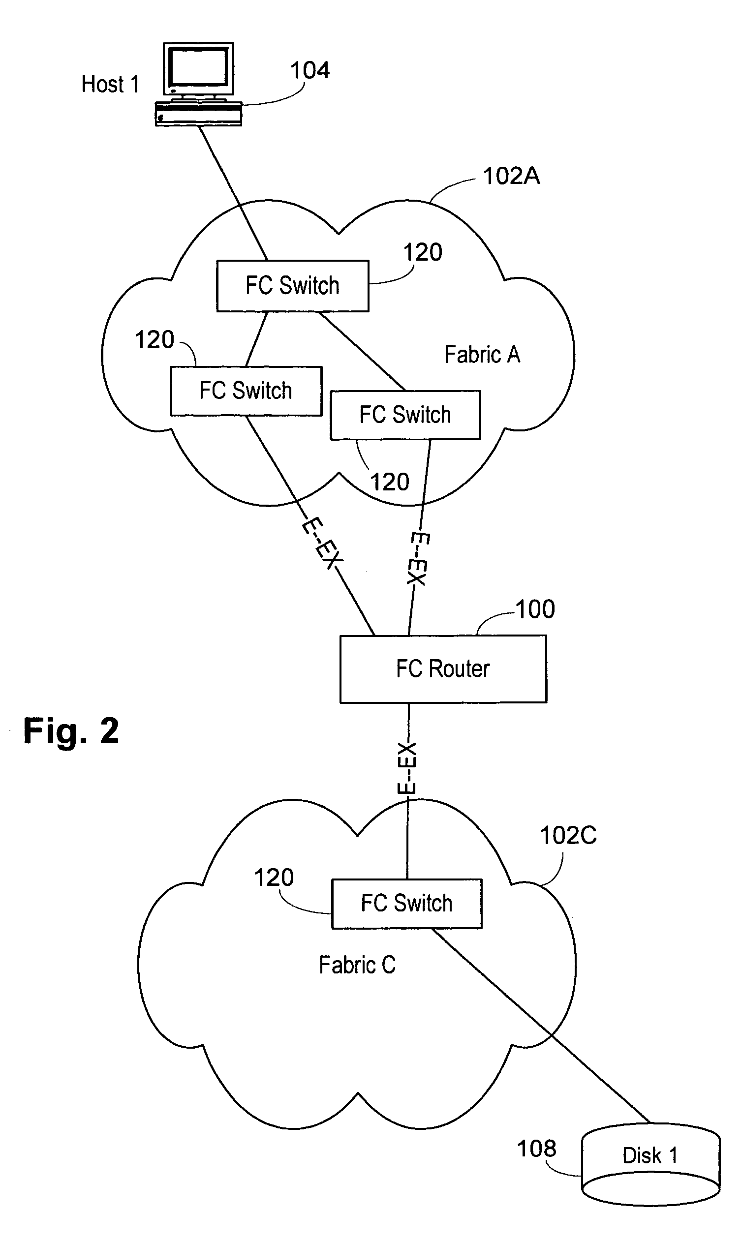
[0040]Referring then to FIG. 2, it can be seen that the fabric A 102A includes a series of Fibre Channel switches 120 which are interconnected to connect to the host 104 and have multiple connections to the Fibre Channel router 100. In the second fabric C 102C, the storage device 108 is connected to a single Fibre Channel switch 120, which has a single link to the Fibre C...
PUM
Abstract
A Fiber Channel router used to join fabrics. EX_ports are used to connect to the fabrics. The EX_port joins the fabric but the router will not merge into the fabric. Ports in the Fiber Channel router can be in a fabric, but other ports can be connected to other fabrics. Fiber Channel routers can be interconnected using a backbone fabric. Global, interfabric and encapsulation headers are developed to allow routing by conventional Fiber Channel switch devices in the backbone fabric and simplify Fiber Channel router routing. Phantom domains and devices must be developed for each of the fabrics being interconnected. Front phantom domains are present at each port directly connected to a fabric. Each of these is then connected to at least one translate phantom domain. Zoning is accomplished by use of a special LSAN zoning naming convention. This allows each administrator to independently define devices are accessible.
Description
CROSS-REFERENCE TO RELATED APPLICATIONS[0001]This application is also related to U.S. patent applications Ser. Nos. 10 / 903,877, entitled “Multifabric Zone Device Import and Export,” by Daniel Chung and Dennis Makishima; Ser. No. 10 / 903,471, entitled “Multifabric Communication Using a Backbone Fabric,” by Dennis Makishima and Daniel Chung; Ser. No. 10 / 909,277, entitled “Multifabric Global Header,” by Steve Wilson, Robert Snively, Ed McClanahan, Dennis Makishima and Daniel Chung; and Ser. No. 10 / 903,899, entitled “Interfabric Routing Header for Use with a Backbone Fabric,” by Robert Snively, Steve Wilson, Ed McClanahan, Dennis Makishima and Daniel Chung, all filed concurrently herewith and hereby incorporated by reference[0002]This application is also related to U.S. patent application Ser. No. 10 / 356,392, entitled “Method and Apparatus for Routing Between Fibre Channel Fabrics,” by Chris Del Signore, Vineet Abraham, Sathish Gnanasekaran, Pranab Patnaik, Vincent W. Guan, and Balakumar...
Claims
Application Information
Patent Timeline
Application Date:The date an application was filed.
Publication Date:The date a patent or application was officially published.
First Publication Date:The earliest publication date of a patent with the same application number.
Issue Date:Publication date of the patent grant document.
PCT Entry Date:The Entry date of PCT National Phase.
Estimated Expiry Date:The statutory expiry date of a patent right according to the Patent Law, and it is the longest term of protection that the patent right can achieve without the termination of the patent right due to other reasons(Term extension factor has been taken into account ).
Invalid Date:Actual expiry date is based on effective date or publication date of legal transaction data of invalid patent.
Patent Type & AuthorityPatents(United States)
IPC IPC(8): H04L12/28H04L12/56
CPCH04L45/04H04L45/60
InventorMAKISHIMA, DENNIS HIDEOCHUNG, DANIEL JI YONG PARK

